第五部分,云中继。通过云中继路由器,实现不同网络之间相互通信。
网络拓扑图如下:
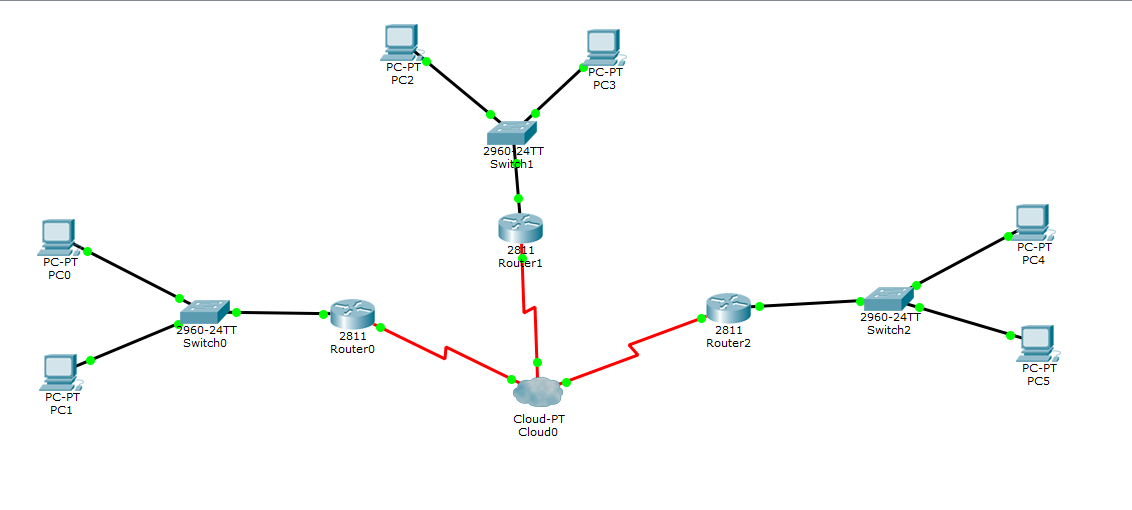
我们需要在每个路由器与云路由器相连的端口配置虚拟接口,以实现与其他网络的通信,配置完成后,拓扑图中的每台pc机之间能够相互通信。
代码:
##基础配置
#r0
en
conf t
int f0/0
ip add 172.168.10.1 255.255.255.0
no shut
int s0/0/0
encapsulation frame-relay
no shut
int s0/0/0.1 point-to-point
ip add 192.168.1.1 255.255.255.0
frame-relay interface-dlci 20
int s0/0/0.2 point-to-point
ip add 192.168.2.1 255.255.255.0
frame-relay interface-dlci 21
exit
router ospf 1
network 192.168.1.0 0.0.0.255 area 1
network 192.168.2.0 0.0.0.255 area 1
network 172.168.10.0 0.0.0.255 area 1
#r1
en
conf t
int f0/0
ip add 172.168.20.1 255.255.255.0
no shut
int s0/0/0
encapsulation frame-relay
no shut
int s0/0/0.1 point-to-point
ip add 192.168.1.2 255.255.255.0
frame-relay interface-dlci 30
int s0/0/0.2 point-to-point
ip add 192.168.3.1 255.255.255.0
frame-relay interface-dlci 31
exit
router ospf 1
network 192.168.1.0 0.0.0.255 area 1
network 192.168.3.0 0.0.0.255 area 1
network 172.168.20.0 0.0.0.255 area 1
#r2
en
conf t
int f0/0
ip add 172.168.30.1 255.255.255.0
no shut
int s0/0/0
encapsulation frame-relay
no shut
int s0/0/0.1 point-to-point
ip add 192.168.3.2 255.255.255.0
frame-relay interface-dlci 40
int s0/0/0.2 point-to-point
ip add 192.168.1.2 255.255.255.0
frame-relay interface-dlci 41
exit
router ospf 1
network 192.168.3.0 0.0.0.255 area 1
network 192.168.1.0 0.0.0.255 area 1
network 172.168.30.0 0.0.0.255 area 1
为每个云中继路由器上每个serial接口的DLCI取别名,方便后面面配置,比如,serial0上的DLCI20,我将它分配给与R1通信,我就取名为toR1:
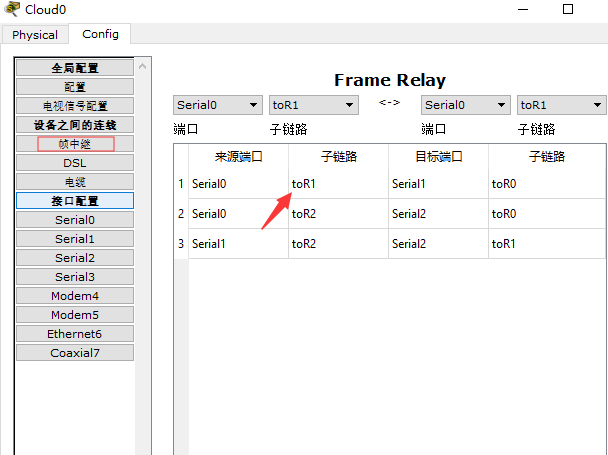
配置云中继,R0要和R1通信,如果从R0到R1这边看,从R0到R1使用Serial0上的toR1,要从R1回到R0,则使用Serial1上的toR0:

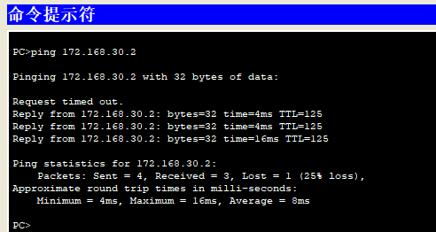
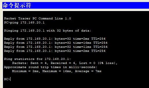
结果检测:
pc0 ping pc2:
pc0 ping pc4: