Introduction
This example shows how to generate sounding reference signals (SRS), as defined in TS 38.211 Section 6.4.1.4, including SRS configuration, symbol and indices generation, OFDM resource grid mapping, and SRS waveform generation.
-
Full-band transmissions: Generate an SRS spanning all the available bandwidth.
-
Frequency-hopping transmissions: Generate periodic and aperiodic SRS transmissions with different frequency-hopping patterns.
-
Multi-user transmissions: Generate orthogonal SRS using time, frequency, and cyclic shifts.
Sounding reference signals are uplink physical signals employed by user equipment (UE) for uplink channel sounding, including channel quality estimation and synchronization. Unlike demodulation reference signals (DM-RS), SRS are not associated to any physical uplink channels and they support uplink channel-dependent scheduling and link adaptation. SRS assist in:
-
Codebook-based closed-loop spatial multiplexing.
-
Control uplink transmit timing.
-
Reciprocity-based downlink precoding in multi-user MIMO setups.
-
Quasi co-location of physical channels and reference signals.
SRS Frequency Positioning
Example of onfiguring a 15 MHz bandwidth carrier with 15 kHz subcarrier spacing (SCS).
carrier = nrCarrierConfig;
carrier.NSizeGrid = 79;             % Bandwidth in RB
carrier.SubcarrierSpacing = 15;

The bandwidth configuration parameters CSRS and BSRS control the bandwidth allocated to the SRS, which normally increases with CSRS and decreases with BSRS.
srs = nrSRSConfig;
srs.CSRS = 10;  % Bandwidth configuration C_SRS (0...63)
srs.BSRS =  1;  % Bandwidth configuration B_SRS (0...3)
srs.FrequencyStart = 30; % Frequency position of the SRS in carrier in RB (0...271)
srs.NRRC = 0;            % Frequency domain position in blocks of 4 PRB (0...67)
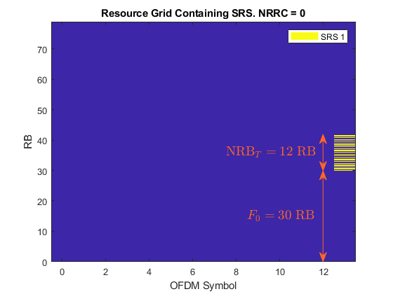
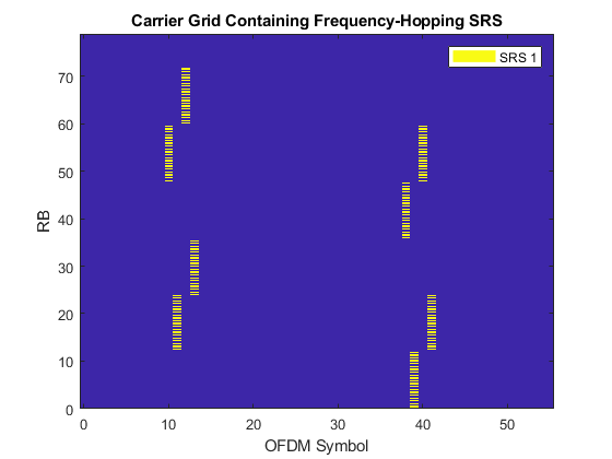
This figure displays a single-slot OFDM resource grid containing an SRS. For CSRS = 10 and BSRS = 1, the frequency position of the SRS (F0) shifts by NRBT when NRRC is in the range (3...5) and by 2NRBT when NRRC is in the range (6...8). The SRS returns to the initial position (FrequencyStart) when NRRC is 9. NRBT is the number of resource blocks (RBs) allocated to the SRS per transmission.
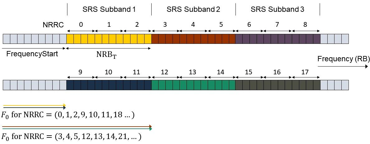
This figure illustrates the concepts introduced above for CSRS = 10 and BSRS = 1.
NRRC is an additional frequency offset specified as a number of 4 RBs and it corresponds to the higher layer parameter freqDomainPosition (see TS 38.331 Section 6.3.2 SRS-Config [2]). For values of NRRC between k⋅(NRBT/4) and (k+1)⋅(NRBT/4)−1, the frequency position of the SRS is shifted by k⋅NRBT, where k is an integer. TS 38.211 Section 6.4.1.4 refers to NRBT as mSRS.b with b=BSRS. For more information, see the NRBPerTransmission property of the nrSRSConfig configuration object.
This equation determines the origin of the SRS in frequency:
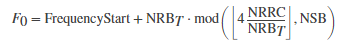
NSB denotes the number of SRS subbands (frequency bands of size NRBT) where the SRS can be positioned through the parameter NRRC. To calculate NSB, you can use the SRS bandwidth configuration table (see TS 38.211 Table 6.4.1.4.3-1).
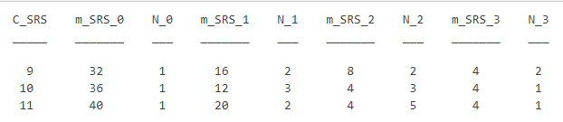
The first column contains possible values of the parameter CSRS. For CSRS = 10 and BSRS = 1, the number of unique SRS subbands is NSB=N0⋯NBSRS=3, where N0=1 and N1=3.
% Calculate and display the number of SRS subbands configurable by NRRC
NSBTable = hSRSNumberOfSubbandsOrHoppingPatterns(srs);

% Number of SRS subbands (NRRC < 9):  3
% Calculate the frequency origin of the first SRS symbol
f0 = hSRSFrequencyOrigin(srs);

% The frequency origin of the SRS is F0 = 30 RB.
When intra-slot frequency hopping is enabled, the calculation of FrequencyOrigin is only valid for the first SRS symbol in the slot.
Frequency-Hopping Configuration
Example of configuring a 15 MHz bandwidth carrier with 15 kHz SCS.
carrier = nrCarrierConfig;
carrier.NSizeGrid = 79;
carrier.SubcarrierSpacing = 15
Create a four-symbol SRS located at the end of the slot. Select the repetition factor to indicate the number of equal consecutive SRS transmissions (OFDM symbols) in a slot. For frequency-hopping configurations, Repetition must be lower than the number of SRS symbols.
srs = nrSRSConfig;
srs.NumSRSSymbols = 4;
srs.Repetition = 1;
srs.SymbolStart = 10; % Time-domain position of the SRS in the slot. (8...13) for normal cyclic prefix (CP) and (6...11) for extended CP
Downlink control information (DCI) can trigger aperiodic SRS transmissions using the higher layer parameter resourceType (see TS 38.331 Section 6.3.2 SRS-Config). As the frequency hopping pattern is reset for aperiodic SRS resource types at each slot, select periodic or semi-persistent SRS resource types to enable inter-slot frequency hopping or aperiodic to disable it. You can configure the slot-wise periodicity and offset of the SRS transmissions by using the property SRSPeriod. For aperiodic resource types, the parameter SRSPeriod controls the periodicity and offset of DCI signals triggering aperiodic SRS transmissions.
srs.ResourceType =  "periodic";
srs.SRSPeriod = [2 0];          % Periodicity in slots (1,2,4,5,8,10,...)
srs.SRSPeriod(2) = 0;           % Offset in slots must be smaller than the periodicity
To select a hopping configuration and observe the changes to the OFDM resource grid.
srs.CSRS = 19; % Bandwidth configuration C_SRS (0...63)
srs.BSRS = 2;  % Bandwidth configuration B_SRS (0...3)
srs.BHop = 0;  % Frequency hopping configuration (0...3). Set BHop >= BSRS to disable frequency hopping
srs.NRRC = 14; % Frequency domain position in blocks of 4 PRB (0...67)
The bandwidth over which the SRS symbols hop increases with the value of CSRS and decreases with BHop (until BHop = BSRS disables hopping). Increasing BSRS reduces the allocated bandwidth per OFDM symbol (property NRBPerTransmission) and can reduce the intra-slot frequency hopping as well. To disable frequency hopping, set BHop >= BSRS. For non-hopping configurations, the roles of CSRS and BSRS are analogous, as the allocated bandwidth increases with CSRS and decreases with BSRS.
You can use the bandwidth configuration table (TS 38.211 Table 6.4.1.4.3-1) to calculate the number of different frequency-hopping patterns configurable by the SRS parameter NRRC as NFHP=NBHop+1⋯NBSRS. The frequency-hopping patterns repeat when NRRC>NFHP⋅NRBT/4.
Set the bandwidth configurations parameters as CSRS = 20, BSRS = 2, and BHop = 1. The condition BHop < BSRS does not guarantee frequency hopping. However, the opposite is true: BHop >= BSRS always disables frequency hopping. You can determine when an SRS bandwidth configuration (CSRS,BSRS,BHop) produces frequency hopping using the Nb parameter from the bandwidth configuration table and evaluating the condition NFHP=NBHop+1⋯NBSRS>1.
Multi-User Configurations
To configure multiple SRS transmissions suitable for multi-user setups, use time-domain, frequency-domain, and sequence-domain parameters can be adopted to create sets of orthogonal (interference-free) SRS transmissions.
Time-Domain Orthogonal SRS
You can create time-domain orthogonal SRS transmissions in multiple ways, for example:
-
Configure different slot periodicity and offset for different SRS by using the property
SRSPeriod. -
Configure different symbol-wise time domain allocations for different SRS by using the property
SymbolStart.
Configure a 10 MHz bandwidth carrier with 15 kHz SCS.
carrier = nrCarrierConfig;
carrier.NSizeGrid = 52;
carrier.SubcarrierSpacing = 15;
To specify the slot periodicity and offset to create orthogonal SRS transmissions.
First SRS configuration:
srs = nrSRSConfig;
srs(1).SRSPeriod = [1 0];
srs(1).SRSPeriod(1) = 4; % Slot periodicity and offset
srs(1).SRSPeriod(2) = 0; % Slot offset of first SRS
Second SRS configuration:
srs(2) = srs(1); % Create a copy of the configured SRS
srs(2).SRSPeriod(1) = 2; % Periodicity in slots
srs(2).SRSPeriod(2) = 1; % Offset in slots
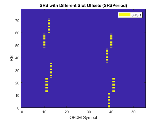
This figure displays an OFDM resource grid containing the configured SRS transmissions.
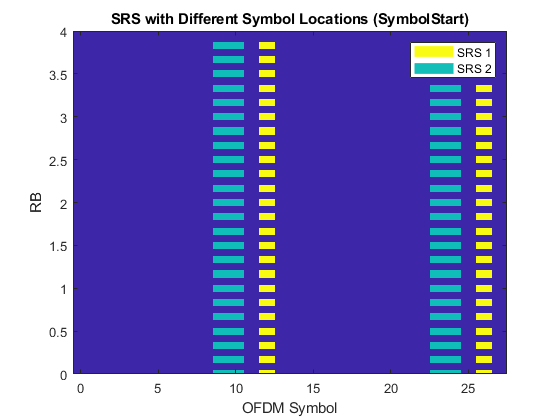
To specify the number of SRS symbols and location in the slot to create orthogonal SRS transmissions.
First SRS configuration:
srs = nrSRSConfig;
srs(1).NumSRSSymbols = 1;  % Number of SRS symbols in a slot (1,2,4)
srs(1).SymbolStart = 12; % Time-domain position of the SRS in the slot. (8...13) for normal cyclic prefix (CP) and (6...11) for extended CP
Second SRS configuration:
srs(2) = srs(1); % Create a copy of the configured SRS
srs(2).NumSRSSymbols = 2;
srs(2).SymbolStart = 9;
This figure displays the OFDM resource grid containing the SRS transmissions.
Frequency-Domain Orthogonal SRS
You can create frequency-domain orthogonal SRS transmissions in multiple ways:
-
Configure different comb offsets for different SRS by using the property
KBarTC. -
Configure different frequency-hopping patterns using
CSRS,BSRS,BHopandNRRC.
Configure a 10 MHz bandwidth carrier with 15 kHz SCS.
carrier = nrCarrierConfig;
carrier.NSizeGrid = 52;
carrier.SubcarrierSpacing = 15;
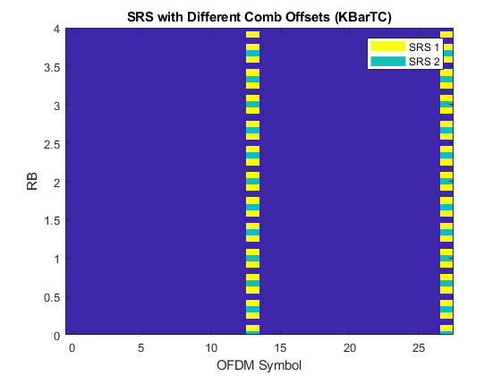
Specify the comb numbers and offsets to create orthogonal SRS transmissions.
First SRS configuration:
srs = nrSRSConfig;
srs(1).KTC    = 2; % Comb number (2,4). It indicates the allocation of the SRS every KTC subcarriers
srs(1).KBarTC = 1; % Comb offset (0...KTC-1)
Second SRS configuration:
srs(2) = srs(1); % Create a copy of the configured SRS
srs(2).KTC    = 4;
srs(2).KBarTC = 0;
This figure displays the OFDM resource grid containing the SRS transmissions.
Create frequency-domain orthogonal SRS configurations using different frequency-hopping patterns.
srs = nrSRSConfig;
srs.NumSRSSymbols = 4;  % Number of SRS symbols in a slot
srs.SymbolStart =8; % Allocate SRS in OFDM symbols 10:13
Select the desired bandwidth configuration parameters, resource type and repetition factor.
srs.CSRS = 10;  % Bandwidth configuration C_SRS (0...63)
srs.BSRS =  2;  % Bandwidth configuration B_SRS (0...3)
srs.BHop =  0;  % Frequency hopping configuration (0...3). Set BHop >= BSRS to disable frequency hopping
srs.ResourceType = "periodic"; % ('periodic','semi-persistent','aperiodic')
srs.Repetition   = 1; % Number of equal consecutive SRS transmissions (1,2,4). It must be lower than NumSRSSymbols
This example calculates the number of orthogonal SRS sequences that can be configured by NRRC and creates frequency non-overlapping SRS configurations. The figure displays the OFDM resource grid containing the SRS transmissions.
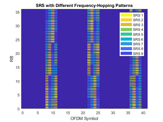
Note that the SRS transmissions are never overlapping regardless of the Repetition factor and ResourceType (aperiodic disables inter-slot frequency hopping). Disable frequency hopping by setting BHop >= BSRS and observe that the different SRS are still allocated to different subbands.
Cyclic-Shift Orthogonal SRS
This section generates multiple SRS allocated to the same time and frequency resources (OFDM symbols and subcarriers) but different time-domain cyclic shifts. Due to the properties of Zadoff-Chu sequences, this configuration produces orthogonal SRS. To demonstrate the orthogonality among the configured SRS, this section performs CP-OFDM modulation and calculates the cross-correlation of the time-domain waveforms.
Matlab Codes,
% Configure a 10 MHz bandwidth carrier with 15 kHz SCS.
carrier = nrCarrierConfig;
carrier.NSizeGrid = 52;
carrier.SubcarrierSpacing = 15;

% Create a full-band SRS
srs = nrSRSConfig;
srs.CSRS = hSRSBandwidthConfiguration(srs,carrier.NSizeGrid);

% All SRS share the same physical resources, but they are configured with different cyclic shifts.
for i = 1:8
    srs(i) = srs(1);
    srs(i).CyclicShift = i-1;
end

% Create a resource grid containing SRS
numSlots = 1; % Numer of slots to generate
for ich = length(srs):-1:1
    slotGrid{ich} = hSRSGrid(carrier,srs(ich),numSlots);
end

% Get OFDM modulation related information
ue.NRB = carrier.NSizeGrid;
ue.SubcarrierSpacing = carrier.SubcarrierSpacing;
ue.CyclicPrefix = carrier.CyclicPrefix;
ofdmInfo = hOFDMInfo(ue);

% OFDM modulation
nsrs = length(srs); % Numer of SRS waveforms
numSamples = numSlots*ofdmInfo.SamplesPerSubframe/ofdmInfo.SlotsPerSubframe;
txWaveform = zeros(numSamples,nsrs);
for i = 1:nsrs
    txWaveform(:,i) = hOFDMModulate(ue,slotGrid{i});
end

% Cross correlation of SRS waveforms generated with different cyclic shifts
C = txWaveform'*txWaveform;
srsCorr = C./diag(C);
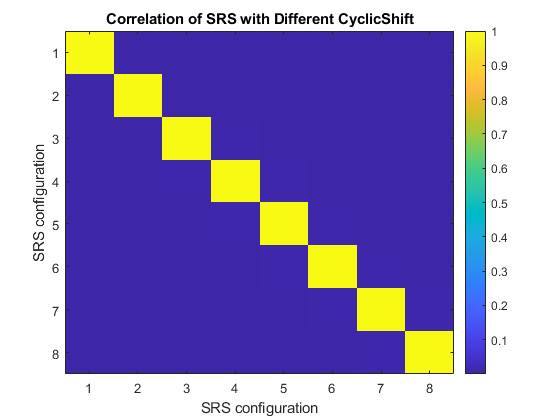
This figure shows the time-domain cross-correlation of the SRS waveforms with different cyclic shifts.
The low correlations among SRS waveforms generated using different time-domain cyclic shifts show their orthogonality.
Conclusion
The relationship between SRS configuration parameters and their effects on both the resource grid and SRS waveform properties:
-
The bandwidth allocated to the SRS generally increases with
CSRSand decreases withBSRS. For frequency-hopping configurations, the instantaneous bandwidth and hopping bandwidth decrease withBSRSandBHop, respectively. -
The frequency position of the SRS depends on the
FrequencyStartandNRRCparameters.NRRCallows to select different SRS subbands and frequency-hopping patterns. -
BHop < BSRSgenerally produces frequency hopping, but it is not guaranteed. However,BHop >= BSRSis sufficient to disable frequency hopping. -
Inter-slot frequency hopping is active only for
periodicandsemi-persistentresource types. -
Time-, frequency-, and sequence-related parameters can be used to create orthogonal SRS transmissions.
Reference
1. 38.211
2. 38.331
3. MathWorks