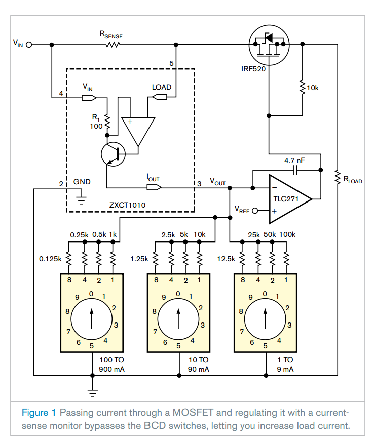
A previous Design Idea describes a programmable current source that used a three-terminal National Semiconductor LM317 adjustable regulator (Reference 1). Although that circuit lets you program the output current, the load current flowed through the BCD (binary-coded-decimal) switches. However, you may find it difficult to purchase BCD switches that can handle more than 25 mA, limiting the circuit’s output current. By applying the simple, four-pin Zetex ZXCT1010 current-sense-monitor chip, you can boost current because it doesn’t flow through BCD switches (Figure 1).

The load current results in a voltage on the sense resistor RSENSE. The voltage on R1, the 100Ω resistor, is the same as that on RSENSE, generating an output current on R1: IOUT×100=ILOAD×RSENSE, and VOUT= IOUT×ROUT, where IOUT is the output current, ILOAD is the load current, and VOUT is the output voltage. You can apply the output voltage as a control voltage to regulate the load current.
One application for this circuit would be to refill accumulators in portable devices. In this case, the circuit works at 18V. The Fairchild SemiconductorIRF520 is an N-channel, power-MOSFET chip in an aluminum heat sink with as much as 9.2A current and 0.27Ω drain-to-source resistance to connect the load current. An op amp controls the IRF520 in the feedback of the load current. In this application, the maximum output current is 1A, and the value of the sense resistor is 0.1Ω. The PCB (printed-circuit board) can also have this small resistance value, which you calculate using the cuprum material’s 35-micron-thick layer. The BCD switches are in parallel and connect from 125Ω to 100 kΩ to adjust the output voltage on the op amp’s negative input. The equations to calculate resistor values are: VSENSE=RSENSE×ILOAD, IOUT=RSENSE×ILOAD/100, and R0=VREF×100/(RSENSE×ILOAD). If you choose a value of 0.1Ω for the sense resistor and a value of 0.1V for the reference voltage, the equation becomes R0=100/ILOAD.
Applying this equation, you can calculate the four weighting resistors of the three BCD switches, which you can determine when the current flows through only that resistor. For currents of 800, 400, 200, 100, 80, 40, 20, 10, 8, 4, 2, and 1 mA, the corresponding resistances would be 0.125, 0.25, 0.5, 1, 1.25, 2.5, 5, 10, 12.5, 25, 50, and 100 kΩ. If the load current is 1A, then the output current is only 1 mA, and, if the load current is 1 mA, then the output current is only 1 μA. Note that the IRF520’s surface is on the drain potential.