This is for Devicetree Specification Release 0.1
Interrupt Mapping Example p19
在講解前,先帶進一些 PCI 的基礎觀念
pci device 的 其中一種 type address 由下方組成

為什麼 硬體要連成這樣子呢? 因為要 loading balance
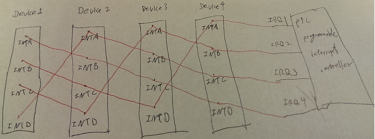
pci device 的 INTA 是較常使用到的,
INTB,INTC,INTD 是較少使用到,
假如每個 device 的 INTA 都發出中斷,這種接線方式會讓 每個中斷 都接到一根 IRQ。
Interrupt Mapping Example p19
有兩個 PCI slots (IDSEL 0x11, 0x12)
每個 slot 有 4 個 中斷 pin, INTA,INTB,INTC,INTD
並且連接到 Open PIC interrupt controller
IDSEL(Initialization Device Select)是指"it used as a chip select during configuration read and write transactions."
這部分會連接到PCI AD[31:11],是由硬體拉線所決定的。
soc {
   compatible = "simple-bus";
   #address-cells = <1>;
   #size-cells = <1>;

   open-pic {
      clock-frequency = <0>;
      interrupt-controller;   // interrupt controller node 需要填寫 interrupt-controller property
      #address-cells = <0>;
      #interrupt-cells = <2>;
   };

   pci {
      #interrupt-cells = <1>;
      #size-cells = <2>;
      #address-cells = <3>;
      interrupt-map-mask = <0xf800 0 0 7>;
      interrupt-map = <
         /* IDSEL 0x11 - PCI slot 1 */
         0x8800 0 0 1 &open-pic 2 1 /* INTA */
         0x8800 0 0 2 &open-pic 3 1 /* INTB */
         0x8800 0 0 3 &open-pic 4 1 /* INTC */
         0x8800 0 0 4 &open-pic 1 1 /* INTD */
         /* IDSEL 0x12 - PCI slot 2 */
         0x9000 0 0 1 &open-pic 3 1 /* INTA */
         0x9000 0 0 2 &open-pic 4 1 /* INTB */
         0x9000 0 0 3 &open-pic 1 1 /* INTC */
         0x9000 0 0 4 &open-pic 2 1 /* INTD */
      >;
   };
};
interrupt-map table 裡的每一列,包含5個部分,
1.child unit address
2.child interrupt specifier
3.interrupt parent
4.parent unit address
5.parent interrupt specifier
child unit address 和 child interrupt specifier 會對應到 特定的 parent unit address 及 interrupt specifier 的 interrupt parent。
interrupt-map table 裡的第一列,
0x8800 0 0 1 &open-pic 2 1
1。child unit address 是 0x8800 0 0
為什麼是由3個 32-bit cells 組成 child unit address?
因為 pci controller 裡的 address-cells property 是3,
所以 PCI bus 是使用 3 個 address cells 來表達 PCI bus。
為什麼是 0x8800?
因為 IDSEL 其中一個是 0x11,這連接到PCI AD[31:11],所以整個 pci address 編碼為 0x8800(編碼方式最上面有提到).
2。child interrupt specifier 是 1
pci controller 的 interrupt-cells 是1,
所以只用一個cell 表達 child interrupt specifier,
而 1 是表達 INTA,(不是從0)
這是指 child interrupt domain,不是 parent interrupt domain。
3。interrupt parent 是 &open-pic
這會填入interrupt parent 的 phandle 的值,來代表 要將 中斷傳給誰(parent)。
4。沒有parent unit address。
因為 parent interrupt domain (open-pic)的 address-cells property 是 0。
5。parent interrupt specifier 是 2 1
parent 的 interrupt-cells 是 2,
所以是使用 2 個 cells 表達 parent interrupt secpfier
2代表 中斷要連到 parent 的 IRQ2。
1代表 level/sense encoding,還不知道這是什麼。
interrupt-map-mask
interrupt-map-mask = <0xf800 0 0 7>
在搜尋 interrupt map table之前,child unit address 及 child interrupt specifier 會先經過
interrupt-map-mask 做 & bit 運算後,得到一個結果,再到 interrupt map talbe 裡取出對應 parent unit address 及 parent interrupt specifier。
Ex:
一個 pci device IDSEL 0x12 (slot 2),function 0x3,發出 INTB 中斷,然後要去 interrupt map talbe 找出 parent open-pic 的 interrupt source number,也就是要找出對應的 parent 中斷 IRQ
pci device 的 address (IDSEL 0x12 (slot 2),function 0x3) 編碼為 0x9300(編碼方式最上面有提到),
因為 pci controller 的 address-cells 為3,所以最後編碼為 0x9300 0 0,
pci device 的 INTB 中斷,編碼為 2,
child unit address及child interrupt specifier整個是 < 0x9300 0 0 2 >。
而<0x9300 0 0 2> 要與 interrupt-map-mask <0xf800 0 0 7> 做 & bit 運算,
得到結果為 <0x9000 0 0 2>,
<0x9000 0 0 2>再往 interrupt map table搜尋 找出,
parent unit address 為空,為什麼為空,因為 parent (open-pic) 的 #address-cells = <0>
parent interrupt specifier 為 <4 1>,對應到 parent (open-pic) 的 IRQ4,1尚未知道其意義,
這樣就完成了 child interrupt domain 到 parent interrupt domain 的轉換
那為什麼要做 interrupt-map-mask 運算呢?
依稀記得網上有篇文章提到,做interrupt-map-mask 運算是要找出那一個 device 發出那一個中斷,所以只保留 bus 及 device bits及 INTx,其它bits 歸零。
reference
http://www.devicetree.org/specifications/
PCI Local Bus Specification Revision 2.2
PCI Read/Write