最好不要直接在标准库中直接查找(不够详细):
 1 /**
 2   * @brief  Writes data to the specified GPIO data port.
 3   * @param  GPIOx: where x can be (A, B, C, D, E or F) to select the GPIO peripheral.
 4   * @note   GPIOC, GPIOD, GPIOE and GPIOF  are available only for STM32F072 and STM32F091.
 5   * @param  GPIO_PinSource: specifies the pin for the Alternate function.
 6   *          This parameter can be GPIO_PinSourcex where x can be (0..15) for GPIOA, GPIOB, GPIOD, GPIOE
 7   *          and (0..12) for GPIOC and (0, 2..5, 9..10) for GPIOF.
 8   * @param  GPIO_AF: selects the pin to used as Alternate function.
 9   *          This parameter can be one of the following value:
10   *            @arg GPIO_AF_0:  WKUP, EVENTOUT, TIM15, SPI1, TIM17, MCO, SWDAT, SWCLK,
11   *                             TIM14, BOOT, USART1, CEC, IR_OUT, SPI2, TIM3, USART4,
12   *                             CAN, USART2, CRS, TIM16, TIM1, TS, USART8
13   *            @arg GPIO_AF_1: USART2, CEC, TIM3, USART1, USART2, EVENTOUT, I2C1,
14   *                            I2C2, TIM15, SPI2, USART3, TS, SPI1, USART7, USART8
15   *                            USART5, USART4, USART6, I2C1
16   *            @arg GPIO_AF_2: TIM2, TIM1, EVENTOUT, TIM16, TIM17, USB, USART6, USART5,
17   *                            USART8, USART7, USART6
18   *            @arg GPIO_AF_3: TS, I2C1, TIM15, EVENTOUT
19   *            @arg GPIO_AF_4: TIM14, USART4, USART3, CRS, CAN, I2C1, USART5
20   *            @arg GPIO_AF_5: TIM16, TIM17, TIM15, SPI2, I2C2, USART6, MCO
21   *            @arg GPIO_AF_6: EVENTOUT
22   *            @arg GPIO_AF_7: COMP1 OUT, COMP2 OUT
23   * @note   The pin should already been configured in Alternate Function mode(AF)
24   *         using GPIO_InitStruct->GPIO_Mode = GPIO_Mode_AF
25   * @note   Refer to the Alternate function mapping table in the device datasheet
26   *         for the detailed mapping of the system and peripherals'alternate
27   *         function I/O pins.
28   * @retval None
29   */
30 void GPIO_PinAFConfig(GPIO_TypeDef* GPIOx, uint16_t GPIO_PinSource, uint8_t GPIO_AF)
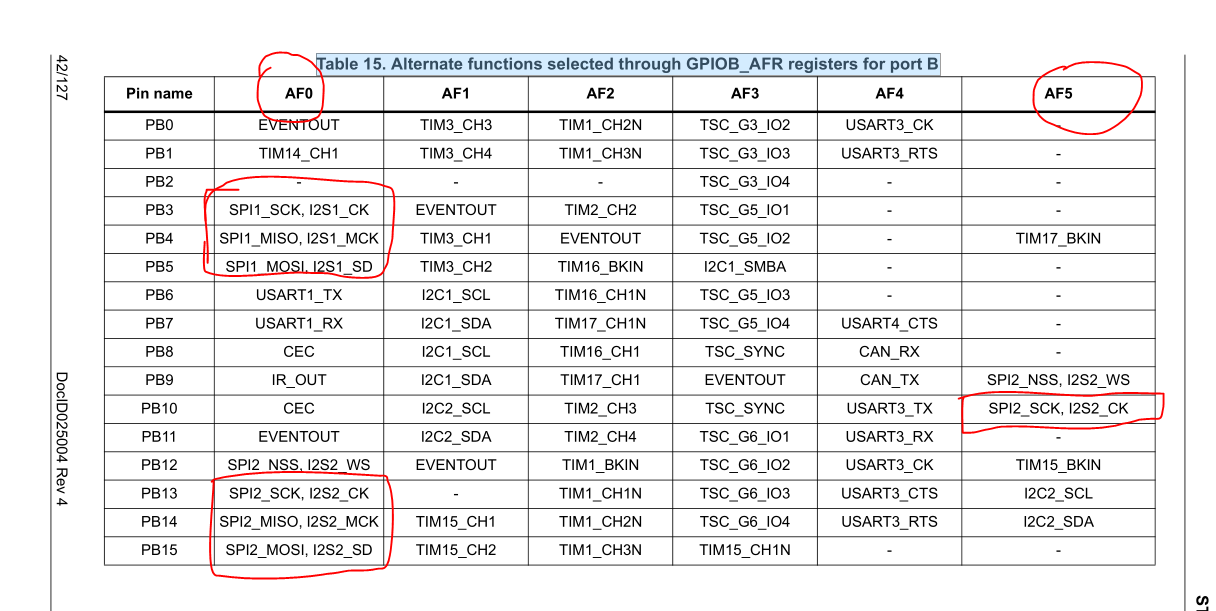
具体操作配置:
// spi2 的初始化
void SPI2_idev_Init( void)
{
    GPIO_InitTypeDef     GPIO_InitStructure;
    SPI_InitTypeDef            SPI_InitStructure;

    RCC_AHBPeriphClockCmd(    RCC_AHBPeriph_GPIOB, ENABLE );
    RCC_APB1PeriphClockCmd(    RCC_APB1Periph_SPI2,  ENABLE );

   GPIO_PinAFConfig(GPIOB, GPIO_PinSource10 , GPIO_AF_5); // 使用的引脚是  PORTB.10
   GPIO_PinAFConfig(GPIOB, GPIO_PinSource14 , GPIO_AF_0);
    GPIO_PinAFConfig(GPIOB, GPIO_PinSource15 , GPIO_AF_0);

    GPIO_InitStructure.GPIO_Pin = GPIO_Pin_15 |GPIO_Pin_14|GPIO_Pin_10;
    GPIO_InitStructure.GPIO_Mode = GPIO_Mode_AF;
    GPIO_InitStructure.GPIO_Speed = GPIO_Speed_Level_3;
    GPIO_InitStructure.GPIO_OType = GPIO_OType_PP;
   GPIO_InitStructure.GPIO_PuPd = GPIO_PuPd_UP;

    GPIO_Init(GPIOB, &GPIO_InitStructure);

    GPIO_SetBits(GPIOB, GPIO_Pin_15 |GPIO_Pin_14|GPIO_Pin_10);

    SPI_I2S_DeInit( SPI2);// 复位
    SPI_InitStructure.SPI_Direction = SPI_Direction_2Lines_FullDuplex;
    SPI_InitStructure.SPI_Mode = SPI_Mode_Master;
    SPI_InitStructure.SPI_DataSize = SPI_DataSize_8b;
    SPI_InitStructure.SPI_CPOL = SPI_CPOL_Low;
    SPI_InitStructure.SPI_CPHA = SPI_CPHA_1Edge;
    SPI_InitStructure.SPI_NSS = SPI_NSS_Soft;
    SPI_InitStructure.SPI_BaudRatePrescaler = SPI_BaudRatePrescaler_2;
    SPI_InitStructure.SPI_FirstBit = SPI_FirstBit_MSB;
    SPI_InitStructure.SPI_CRCPolynomial = 7;
    SPI_Init(SPI2, &SPI_InitStructure);
    SPI_RxFIFOThresholdConfig( SPI2,SPI_RxFIFOThreshold_QF); // 与stm32f1xx 主要区别点

    SPI_Cmd(SPI2, ENABLE);
}
// SPI 写8位
void SPI2_WriteByte(uint8_t data)
{
    while((SPI2->SR&SPI_I2S_FLAG_TXE)==RESET); // 等待发送区为空
      SPI_SendData8(SPI2,data);
}
// SPI 读写
uint8_t drv_spi_read_write_byte( uint8_t TxByte )
{
    uint16_t retry=0;

    while (SPI_I2S_GetFlagStatus(SPI2, SPI_I2S_FLAG_TXE) == RESET) // 等待发送区为空
    {
      retry++;
      if(retry>400) {
        return 0;
      }
    }
      SPI_SendData8(SPI2, TxByte);
      retry=0;

    while (SPI_I2S_GetFlagStatus(SPI2, SPI_I2S_FLAG_RXNE) == RESET) //等待接收缓冲区为空
    {
      retry++;
      if(retry>400)
      {
        return 0;
       }
    }
      return SPI_ReceiveData8(SPI2);
}
这样就基本没有什么问题的啦