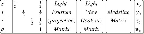
在使用阴影映射(shadow maping)实现阴影时,《The Cg Tutorial》中使用了投影纹理。其中生成投影纹理坐标的纹理矩阵的生成过程由下图所示:
其官方教程的说明如下:
Let's go through the transformations, to clarify what's going on. The vertices start in object coordinates.
- Multiply by the modeling matrix. This applies any necessary modeling transformations to the vertices. The modeling matrix needs to be applied regardless of whether or not you're using projective texturing.
- Multiply by the light's viewing matrix. This rotates and translates the vertices so that they are in the light's frame of reference.
- Multiply by the light's projection matrix. This defines the light's frustum, including its field of view and aspect ratio.
- Scale and bias the results. Following steps 1 to 3, the transformed vertex values range from -1 to 1. However, textures are indexed from 0 to 1, so the results have to be mapped to this range. This is done by multiplying the x, y, and z components of the results by ½ and then adding ½. A single matrix multiplication accomplishes this mapping.
当时看的时候对其中标红的部分感到匪夷所思,因为在我的印象中经过前三步后的将坐标转到的裁剪空间(clip space)貌似不是在(-1,1)的范围(难道我记错了! ),之后我就开始找资料,看看是不是这么一回事(参考我之前的随笔“【转载】齐次坐标概念&&透视投影变换推导”)。结论是裁剪空间三个坐标分量的范围都是(-w,w),原来真的是《The Cg Tutorial》中的说法有误!
---------------------------------------------------------
后来看了Cg Toolkit中的Sample 27_projective_texturing后发现,其实它的文中这么写也无可厚非,目的是让人更加容易理解。因为它的源码中是使用了tex2Dproj()这个专用的投影采样函数。那它与我们常用的tex2D()有什么不一样的地方呢?于是我查了工具包中的Reference Manual,其说明如下:
DESCRIPTION
Performs a texture lookup in sampler samp using coordinates s, the coordinates used in the lookup are first projected, that is, divided by the last component of the coordinate vector and them used in the lookup. If an extra coordinate is present it is used to perform a shadow comparison, the value used in the shadow comparison is always the next-to-last component in the coordinate vector.
大意就是在查询纹理的时候对其纹理坐标做了一次投影,即除以了纹理坐标的最后一个分量。上文提到裁剪空间的坐标范围是(-w,w),那么经过一次“Scale and Bias”之后其表述范围就是(0,w),再在tex2Dproj()中纹理坐标投影后不就是(0,1)了吗?此时,我已恍然大悟 。
。
---------------------------------------------------------
知道原因后,其实直接用tex2D()来实现tex2Dproj()的功能也仅仅是在纹理坐标上手动除以其最后一个分量(这里补充一下:其实tex2D本身就已经有tex2Dproj的功能,完全可以代替tex2Dproj使用!说白了就是有用tex2Dproj的地方都可以用tex2D代替,反之不成立。这是我后来在Cg Reference中发现的,之前没有注意到而已啦),如下:
  float4 textureColor = tex2Dproj(projectiveMap,
                                  texCoordProj);

  float4 textureColor = tex2D(projectiveMap,
                                  texCoordProj.xy/texCoordProj.w);
想想看,其实也可以在生成Texture Matrix的时候去掉最后一步(Scale and Bias),直接取光源的MVP(ModelView_Projection)矩阵作为投影纹理矩阵,不过相应地也需要在纹理查询时对其纹理坐标进行一次变换,示例代码如下:
  float4 textureColor = tex2D(projectiveMap,
                                  texCoordProj.xy/texCoordProj.w*0.5+0.5);
后面的*0.5+0.5算是对之前”偷工减料”的弥补了!