This is an old arduino 3G module bought half years ago.
Its wiki:
http://wiki.iteadstudio.com/ITEAD_3G_Shield
Its mall:
http://imall.itead.cc/itead-3g-shield.html
But as you can see that, the download link does not exist anymore. But after googling a bit, there are some alternatives for you to download the goodies.
Datasheet for ITEAD 3G Shield http://pan.baidu.com/s/1ntCH4UH
Schematic for ITEAD 3G Shield http://pan.baidu.com/s/1pJ5lRzt
Demo Code for ITEAD 3G Shield http://pan.baidu.com/s/1gdyaCYf

Its back where you insert a SIM card:

On arduino, switch VCC to 5V, switch Flight mode , RF to be On.
And for the UART multiplexer on the board,
When using the connection as Figure 4, the SIM900 connect to the ATMega328 chip on board.
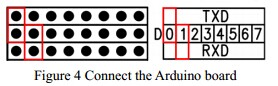
Pin D0 Tx on 3G shield <-----> Rx on Arduino
Pin D1 Rx on 3G shield <-----> Tx on Arduino
To test whether your board is working:
void setup()
{
  Serial.begin(115200);
}

void loop()
{
  while(1)

  {
    // dail 13988899999
  Serial.print("ATD13988899999;
");

  delay(5000);
  }

}
This is gonna dial this number 13988899999 forever.
If you receive a call, your module is working perfectly.
This board uses AT commands to control itself.
Key: AT commands
What is AT commands?
For Chinese readers: http://baike.baidu.com/view/2420376.htm
For English readers: https://en.wikipedia.org/wiki/Motorola_phone_AT_commands ( This is very helpful )
The AT commands manual those are compatible for this board can be found here.
http://wiki.iteadstudio.com/images/2/20/SIM5215J_SIM5216J_AT_Command_Manual_V1.02.pdf
Or here: http://pan.baidu.com/s/1kDDQu (You do not need to be an expert)
It looks the manual is long enough to make you sleepy. :P Just check the exquisite down below.
You can find helpful tutorials from Arduino offcial forum:
http://forum.arduino.cc/index.php?topic=140526.0
And the problem was solved. You can use that scope of codes.
Setting the UART multiplexer

If you do not know anything about UART multiplexer, you could check it out here. http://wiki.iteadstudio.com/IComSat
From its schema:
It looks like this:

Play with the jumpers on the board.
It would looks like this before:
then re-set it to be like this:
Now you program on it.
Let's try some AT commands:
Send command:
ATI
You would get these in return:
ATI

Manufacturer: SIMCOM INCORPORATED
Model: SIMCOM_SIM5216E
Revision: SIM5216E_V1.5
IMEI: 359769033240570
+GCAP: +CGSM,+DS,+ES

OK
To the UART SoftwareSerial ports.
If you want to debug this 3G shield module with arduino, PC , you should set baud rate to be 9600 or less.
The rate of 115200 is too high for SoftwareSerial on Arduino. ( That's why here later I used a FT232 USB2Serial module on PC to communicate with this 3G shield without arduino. )
It looks as what he said: http://forum.arduino.cc/index.php?topic=140526.msg1653999#msg1653999
Using A FT232 USB -> Serial module to control 3G module ( No arduino at all )

Sources from:
http://www.elecfreaks.com/wiki/index.php?title=3G_shield
See how I did it for real.

Settings with jumpers on shield:

On FT232 USB2Serial module :

Tx on FT232 <--> Rx on 3G module
Rx on FT232 <--> Tx on 3G module
Here I used cutecom on Linux.
Please notice the settings below:

Send in Plain text and select "CR line end".
If you want to dail one's number, for example, 18612341234, just input
ATD18612341234;
It works well. And with MIC and Phone, you can speak and hear from the other one.