Identifier filtering
In the CAN protocol the identifier of a message is not associated with the address of a node but related to the content of the message.
Consequently a transmitter broadcasts its message to all receivers.
On message reception a receiver node decides - depending on the identifier value - whether the software needs the message or not.
If the message is needed, it is copied into the SRAM.
If not, the message must be discarded without intervention by the software.
To fulfill this requirement, the bxCAN Controller provides 28 configurable and scalable filter banks (27-0) to the application.
In other devices the bxCAN Controller provides 14 configurable and scalable filter banks (13-0) to the application
in order to receive only the messages the software needs.
This hardware filtering saves CPU resources which would be otherwise needed to perform filtering by software.
Each filter bank x consists of two 32-bit registers, CAN_FxR0 and CAN_FxR1. = 2 * 28 = 56 Registers

Scalable width
To optimize and adapt the filters to the application needs, each filter bank can be scaled independently.
Depending on the filter scale a filter bank provides:
One 32-bit filter for the STDID[10:0], EXTID[17:0], IDE and RTR bits.
Two 16-bit filters for the STDID[10:0], RTR, IDE and EXTID[17:15] bits.
Furthermore, the filters can be configured in mask mode or in identifier list mode.
Mask mode
In mask mode the identifier registers are associated with mask registers specifying
which bits of the identifier are handled as must match or as dont care.
Each bit of the register specifies whether the bit of the associated identifier register
must match with the corresponding bit of the expected identifier or not.
0: Dont care, the bit is not used for the comparison --- Don't Care
1: Must match, the bit of the incoming identifier must have the same level
has specified in the corresponding identifier register of the filter -- Do Care.
Identifier list mode
In identifier list mode, the mask registers are used as identifier registers.
Thus instead of defining an identifier and a mask, two identifiers are specified,
doubling the number of single identifiers.
All bits of the incoming identifier must match the bits specified in the filter registers.
Each bit of the register specifies the level of the corresponding bit of the expected identifier.
0: Dominant bit is expected
1: Recessive bit is expected
Filter bank scale and mode configuration
The filter banks are configured by means of the corresponding CAN_FMR register.
To configure a filter bank it must be deactivated by clearing the FACT bit in the CAN_FAR register.
The filter scale is configured by means of the corresponding FSCx bit in the CAN_FS1R register, refer to Figure 342.
The identifier list or identifier mask mode for the corresponding Mask/Identifier registers is configured
by means of the FBMx bits in the CAN_FMR register.
To filter a group of identifiers, configure the Mask/Identifier registers in mask mode.
To select single identifiers, configure the Mask/Identifier registers in identifier list mode.
Filters not used by the application should be left deactivated.
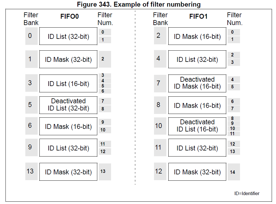
Each filter within a filter bank is numbered (called the Filter Number)
from 0 to a maximum dependent on the mode and the scale of each of the filter banks.
Concerning the filter configuration, refer to Figure 342.
Filter match index
Once a message has been received in the FIFO it is available to the application.
Typically, application data is copied into SRAM locations.
To copy the data to the right location the application has to identify the data by means of the identifier.
To avoid this, and to ease the access to the SRAM locations, the CAN controller provides a Filter Match Index.
This index is stored in the mailbox together with the message according to the filter priority rules.
Thus each received message has its associated filter match index.
The Filter Match index can be used in two ways:
Compare the Filter Match index with a list of expected values.
Use the Filter Match Index as an index on an array to access the data destination location.
For nonmasked filters, the software no longer has to compare the identifier.
If the filter is masked the software reduces the comparison to the masked bits only.
The index value of the filter number does not take into account the activation state of the
filter banks. In addition, two independent numbering schemes are used, one for each FIFO.
Refer to Figure 343 for an example.
Filter priority rules
Depending on the filter combination it may occur that an identifier passes successfully through several filters.
In this case the filter match value stored in the receive mailbox is chosen according to the following priority rules:
A 32-bit filter takes priority over a 16-bit filter.
For filters of equal scale, priority is given to the Identifier List mode over the Identifier Mask mode
For filters of equal scale and mode, priority is given by the filter number (the lower the number, the higher the priority).

The example above shows the filtering principle of the bxCAN. On reception of a message, the identifier is compared first with the filters configured in identifier list mode.
If there is a match, the message is stored in the associated FIFO and the index of the matching filter is stored in the Filter Match Index.
As shown in the example, the identifier matches with Identifier #2 thus the message content and FMI 2 is stored in the FIFO.
If there is no match, the incoming identifier is then compared with the filters configured in mask mode.
If the identifier does not match any of the identifiers configured in the filters, the message is discarded by hardware without disturbing the software.