原文链接:https://blog.51cto.com/692344/1075579
原文链接:https://blog.csdn.net/weixin_34205826/article/details/91530936
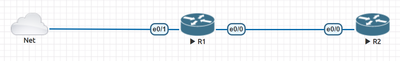
图中的R1作为LAC,R2作为LNS,Net桥接到物理网卡
LAC:
hostname lac
aaa new-model
aaa authentication ppp default none
vpdn enable
vpdn search-order domain
vpdn-group 1
request-dialin
protocol l2tp
domain fc.ln
initiate-to ip 1.1.2.2
local name LAC
no l2tp tunnel authentication
bba-group pppoe global
virtual-template 1
interface Ethernet0/0
ip address 1.1.2.1 255.255.255.0
interface Ethernet0/1
ip address dhcp
pppoe enable group global
interface Virtual-Template1
mtu 1492
ip unnumbered Ethernet0/1
no peer default ip address
ppp authentication pap chap
LNS:
hostname lns
aaa new-model
aaa authentication ppp vpdn local
vpdn enable
!
vpdn-group 1
accept-dialin
protocol l2tp
virtual-template 1
terminate-from hostname LAC
lcp renegotiation always
no l2tp tunnel authentication
!
!
username lnsuser@fc.ln password 0 lnsuser
!
interface Ethernet0/0
ip address 1.1.2.2 255.255.255.0
!
interface Virtual-Template1
ip unnumbered Ethernet0/0
peer default ip address pool mypool
ppp authentication pap chap vpdn
!
ip local pool mypool 192.168.0.10 192.168.0.20
图中的network是桥接到我自己的VMware网卡了
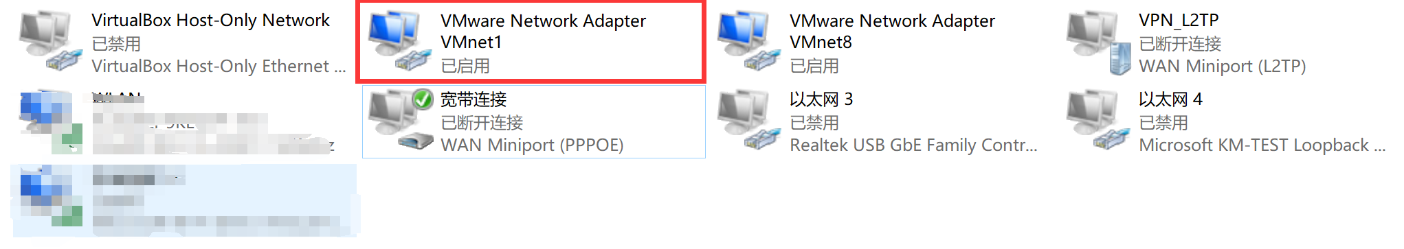
桥接完成后,从物理机ping一下模拟器里面的R1
可以看出从VMware 网卡VMnet1的DHCP服务器中获取到的IP地址为192.168.229.136,用物理机ping 192.168.229.136如果可以ping通,则认为网络连通性正常,可以继续进行拨号配置;
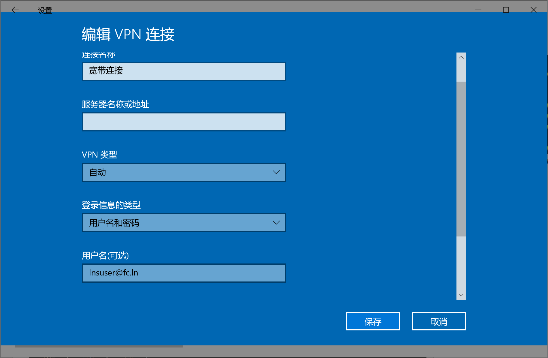
进行拨号配置