18.1 设备树的起源
linux 2.6及之前,大量板级信息被硬编码到内核里,十分庞大,大量冗余代码;
linux 2.6之前,引入了设备树;
设备树源于OpenFirmware,描述硬件的数据结构。由一些列节点node和属性property组成,通常包括下列信息:
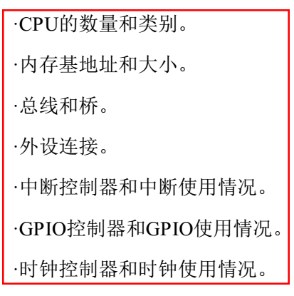
本质上是画一棵CPU、总线、设备组成的树,Linux内核会把设备树展开成platform_device、i2c_client、spi_device等设备,而这些设备用到的内存、中断等资源,也会传递个内核,内核会将这些资源绑定给展开的相应设备。
18.2 设备树的组成和结构
18.2.1 DTS/DTC/DTB
dts:文本
dtc:编译dts的
dtb:编译后的二进制文件
绑定:documentation/devicetree/bindings/***,描述各硬件的dts格式,不一定及时更新,但可作为参考。
以下为dts的结构:
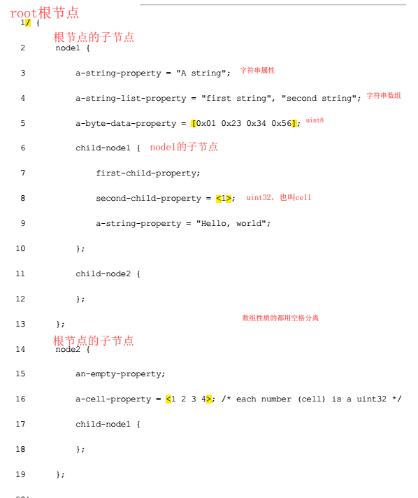
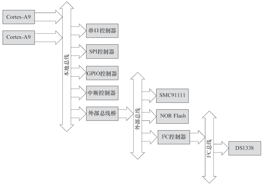
描述上图属性结构的示例dts为:
1/ {
2     compatible = "acme,coyotes-rev
3     #address-cells = <1>;  // 描述下一级子节点的数据属性
4     #size-cells = <1>;
5     interrupt-parent = <&intc>;
6
7     cpus {
8       #address-cells = <1>;
9       #size-cells = <0>;
10       cpu@0 {
11         compatible = "arm,cortex-a9";   // device兼容性,用于与driver匹配
12         reg = <0>;
13       };
14       cpu@1 {
15         compatible = "arm,cortex-a9";
16         reg = <1>;
17       };
18    };
19
20    serial@101f0000 {        // 地址
21      compatible = "arm,pl011";
22       reg = <0x101f0000 0x1000 >;
23      interrupts = < 1 0 >;
24     };
25
26    serial@101f2000 {
27      compatible = "arm,pl011";
28       reg = <0x101f2000 0x1000 >;
29      interrupts = < 2 0 >;
30    };
31
32    gpio@101f3000 {
33      compatible = "arm,pl061";
34      reg = <0x101f3000 0x1000
35      0x101f4000 0x0010>;
36      interrupts = < 3 0 >;
37    };
38
39     intc: interrupt-controller@10140000 {
40      compatible = "arm,pl190";
41       reg = <0x10140000 0x1000 >;
42      interrupt-controller;
43      #interrupt-cells = <2>;
44    };
45
46    spi@10115000 {
47      compatible = "arm,pl022";
48      reg = <0x10115000 0x1000 >;
49      interrupts = < 4 0 >;50    };
51
52    external-bus {
53      #address-cells = <2>
54      #size-cells = <1>;
55      ranges = <0 0 0x10100000 0x10000 // Chipselect 1, Ethernet
56            1 0 0x10160000 0x10000 // Chipselect 2, i2c controller
57            2 0 0x30000000 0x1000000>; // Chipselect 3, NOR Flash
58
59      ethernet@0,0 {
60        compatible = "smc,smc91c111";
61        reg = <0 0 0x1000>;
62        interrupts = < 5 2 >;
63      };
64
65      i2c@1,0 {
66        compatible = "acme,a1234-i2c-bus";
67        #address-cells = <1>;
68        #size-cells = <0>;
69        reg = <1 0 0x1000>;
70        interrupts = < 6 2 >;
71        rtc@58 {
72          compatible = "maxim,ds1338";
73          reg = <58>;
74          interrupts = < 7 3 >;
75        };
76     };
77
78     flash@2,0 {
79       compatible = "samsung,k8f1315ebm", "cfi-flash";
80       reg = <2 0 0x4000000>;
81     };
82   };// end of external-bus
83};
18.2.2 根节点兼容性
18.2.2.1 实现芯片型号相关初始化
根节点的兼容性,一般格式如下(以ZYNQ为例):
dts:
compatible = "xlnx,zynq-7000";  // 厂商、型号


内核代码:
static const char * const zynq_dt_match[] = {
    "xlnx,zynq-7000",
    NULL
};

// 匹配后,DT_MACHINE_START到MACHINE_END之间的函数会被执行,arch/arm/mach-zynq/common.c
DT_MACHINE_START(XILINX_EP107, "Xilinx Zynq Platform")
    .smp        = smp_ops(zynq_smp_ops),
    .map_io        = zynq_map_io,
    .init_irq    = zynq_irq_init,
    .init_machine    = zynq_init_machine,
    .init_late    = zynq_init_late,
    .init_time    = zynq_timer_init,
    .dt_compat    = zynq_dt_match,
    .reserve    = zynq_memory_init,
    .restart    = zynq_system_reset,
MACHINE_END

#define DT_MACHINE_START(_name, _namestr)
static const struct machine_desc __mach_desc_##_name
 __used
 __attribute__((__section__(".arch.info.init"))) = {
    .nr        = ~0,
    .name        = _namestr,

#define MACHINE_END
};
18.2.2.2 提倡同类型号归一处理
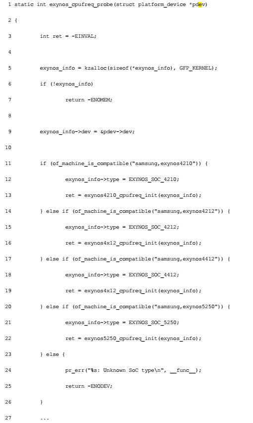
同一类型的芯片,可以使用同一的初始化接口,用OF的API判断根节点兼容性字段,走不同分支。
/**
 * of_machine_is_compatible - Test root of device tree for a given compatible value
 * @compat: compatible string to look for in root node's compatible property.
 *
 * Returns true if the root node has the given value in its
 * compatible property.
 */
int of_machine_is_compatible(const char *compat)
{
    struct device_node *root;
    int rc = 0;

    root = of_find_node_by_path("/");
    if (root) {
        rc = of_device_is_compatible(root, compat);
        of_node_put(root);
    }
    return rc;
}
EXPORT_SYMBOL(of_machine_is_compatible);
18.2.3 设备节点兼容性
表示device的兼容性, 用于与driver匹配。
zynq i2c匹配示例

dts:
        ps7_i2c_1: ps7-i2c@e0005000 {
            clock-frequency = <400000>;
            clocks = <&clkc 39>;
            compatible = "cdns,i2c-r1p10";
            interrupt-parent = <&ps7_scugic_0>;
            interrupts = <0 48 4>;
            reg = <0xe0005000 0x1000>;
            xlnx,has-interrupt = <0x0>;
            #address-cells = <1>;
            #size-cells = <0>;
            eeprom@52 {
                compatible = "at,24c512";
                reg = <0x52>;
            };
        } ;


static const struct of_device_id cdns_i2c_of_match[] = {
    { .compatible = "cdns,i2c-r1p10", },
    { /* end of table */ }
};
MODULE_DEVICE_TABLE(of, cdns_i2c_of_match);

static struct platform_driver cdns_i2c_drv = {
    .driver = {
        .name  = DRIVER_NAME,
        .owner = THIS_MODULE,
        .of_match_table = cdns_i2c_of_match,
        .pm = &cdns_i2c_dev_pm_ops,
    },
    .probe  = cdns_i2c_probe,
    .remove = cdns_i2c_remove,
};


// i2c总线负责匹配
struct bus_type i2c_bus_type = {
    .name        = "i2c",
    .match        = i2c_device_match,
    .probe        = i2c_device_probe,
    .remove        = i2c_device_remove,
    .shutdown    = i2c_device_shutdown,
    .pm        = &i2c_device_pm_ops,
};
EXPORT_SYMBOL_GPL(i2c_bus_type);


static int i2c_device_match(struct device *dev, struct device_driver *drv)
{
    struct i2c_client    *client = i2c_verify_client(dev);
    struct i2c_driver    *driver;

    if (!client)
        return 0;

    /* Attempt an OF style match */
    if (of_driver_match_device(dev, drv))
        return 1;

    /* Then ACPI style match */
    if (acpi_driver_match_device(dev, drv))
        return 1;

    driver = to_i2c_driver(drv);
    /* match on an id table if there is one */
    if (driver->id_table)
        return i2c_match_id(driver->id_table, client) != NULL;

    return 0;
}
18.2.4 设备节点及label的命名
设备节点采用 <name>[@<unit-address>]的格式,[ ]为可选项。挂到内存空间的设备,unit-address一般是内存地址。
还可以为节点创建标签,别的地方引用时可以用标签。
ps7_gpio_0: ps7-gpio@e000a000 {    // 标签 : 节点
            #gpio-cells = <2>;
            clocks = <&clkc 42>;
            compatible = "xlnx,zynq-gpio-1.0";
            emio-gpio-width = <64>;
            gpio-controller ;
            gpio-mask-high = <0x0>;
            gpio-mask-low = <0x5600>;
            interrupt-parent = <&ps7_scugic_0>;
            interrupts = <0 20 4>;
            reg = <0xe000a000 0x1000>;
        } ;


ps7_ethernet_0: ps7-ethernet@e000b000 {
            ...
            enet-reset = <&ps7_gpio_0 11 0>;  // 引用标签
            ...
        } ;
18.2.5 地址编码
1. #address-cells和#size-cells
// 父节点的address-cells和size-cells决定子节点的reg的address和lenth字段的长度,cell的单位为32bit
#address-cells  // 子节点reg的address为几个32bit的整型数据
#size-cells    // 长度为几个32bit整型数据,如果为0,则没有lenth字段

node{
      reg = <address1 lenth1 [address2 lenth2] [address3 lenth3]...>;
}
    ps7_axi_interconnect_0: amba@0 {
        #address-cells = <1>;  // 下一级节点reg的address字段长度为1个32bit,下一级节点为ps7-i2c@e0005000
        #size-cells = <1>;     // 下一级节点reg的len字段长度为1个32bit

        ...
        ps7_i2c_1: ps7-i2c@e0005000 {
            clock-frequency = <400000>;
            clocks = <&clkc 39>;
            compatible = "cdns,i2c-r1p10";
            interrupt-parent = <&ps7_scugic_0>;
            interrupts = <0 48 4>;
            reg = <0xe0005000 0x1000>;  // 地址为0xe0005000,长度为0x1000
            xlnx,has-interrupt = <0x0>;
            #address-cells = <1>;  // 下一级eeprom的reg属性
            #size-cells = <0>;     // 没有len字段
            eeprom@52 {
                compatible = "at,24c512";
                reg = <0x52>;    // 地址为0x52,没有长度字段
            };
        } ;
        ...
    }
18.2.6 中断连接
- interrutt-controller,属性为空,表明“我是中断控制器”
- #interrupt-cells,表明连接此中断控制器的设备的中断属性的cell大小,也就是interrupt = <>属性的cell大小
- interrupt-parent,设备节点通过这个关键字指定其依附的中断控制器phandle,如果没有指定,则继承父节点的interrupt-parent配置
- interrupt,设备节点里使用,一般包含中断号、触发方法等。具体有多少个cell,由#interrupt-cells决定,每个cell的具体含义,一般由驱动的实决定,一般会在绑定文件里说明,下面是arm interrupt的绑定文件:3个cell,1st是种类(spi/ppi),2st是中断号,3st是flag
Documentation/devicetree/bindings/arm/gic.txt

* ARM Generic Interrupt Controller

ARM SMP cores are often associated with a GIC, providing per processor
interrupts (PPI), shared processor interrupts (SPI) and software
generated interrupts (SGI).

Primary GIC is attached directly to the CPU and typically has PPIs and SGIs.
Secondary GICs are cascaded into the upward interrupt controller and do not
have PPIs or SGIs.

Main node required properties:

- compatible : should be one of:
    "arm,gic-400"
    "arm,cortex-a15-gic"
    "arm,cortex-a9-gic"
    "arm,cortex-a7-gic"
    "arm,arm11mp-gic"
- interrupt-controller : Identifies the node as an interrupt controller
- #interrupt-cells : Specifies the number of cells needed to encode an
  interrupt source.  The type shall be a <u32> and the value shall be 3.

  The 1st cell is the interrupt type; 0 for SPI interrupts, 1 for PPI
  interrupts.

  The 2nd cell contains the interrupt number for the interrupt type.
  SPI interrupts are in the range [0-987].  PPI interrupts are in the
  range [0-15].

  The 3rd cell is the flags, encoded as follows:
    bits[3:0] trigger type and level flags.
        1 = low-to-high edge triggered
        2 = high-to-low edge triggered
        4 = active high level-sensitive
        8 = active low level-sensitive
    bits[15:8] PPI interrupt cpu mask.  Each bit corresponds to each of
    the 8 possible cpus attached to the GIC.  A bit set to '1' indicated
    the interrupt is wired to that CPU.  Only valid for PPI interrupts.

- reg : Specifies base physical address(s) and size of the GIC registers. The
  first region is the GIC distributor register base and size. The 2nd region is
  the GIC cpu interface register base and size.

Optional
- interrupts    : Interrupt source of the parent interrupt controller on
  secondary GICs, or VGIC maintenance interrupt on primary GIC (see
  below).

- cpu-offset    : per-cpu offset within the distributor and cpu interface
  regions, used when the GIC doesn't have banked registers. The offset is
  cpu-offset * cpu-nr.

Example:

    intc: interrupt-controller@fff11000 {
        compatible = "arm,cortex-a9-gic";
        #interrupt-cells = <3>;
        #address-cells = <1>;
        interrupt-controller;
        reg = <0xfff11000 0x1000>,
              <0xfff10100 0x100>;
    };


* GIC virtualization extensions (VGIC)

For ARM cores that support the virtualization extensions, additional
properties must be described (they only exist if the GIC is the
primary interrupt controller).

Required properties:

- reg : Additional regions specifying the base physical address and
  size of the VGIC registers. The first additional region is the GIC
  virtual interface control register base and size. The 2nd additional
  region is the GIC virtual cpu interface register base and size.

- interrupts : VGIC maintenance interrupt.

Example:

    interrupt-controller@2c001000 {
        compatible = "arm,cortex-a15-gic";
        #interrupt-cells = <3>;
        interrupt-controller;
        reg = <0x2c001000 0x1000>,
              <0x2c002000 0x1000>,
              <0x2c004000 0x2000>,
              <0x2c006000 0x2000>;
        interrupts = <1 9 0xf04>;
    };
        ps7_scugic_0: ps7-scugic@f8f01000 {
            #address-cells = <2>;
            #interrupt-cells = <3>;   // 设备节点的interrupt属性有3个cells
            #size-cells = <1>;
            compatible = "arm,cortex-a9-gic", "arm,gic";
            interrupt-controller ;   // 我是中断控制器
            num_cpus = <2>;
            num_interrupts = <96>;
            reg = <0xf8f01000 0x1000>, <0xf8f00100 0x100>;
        } ;
        ps7_i2c_1: ps7-i2c@e0005000 {
            clock-frequency = <400000>;
            clocks = <&clkc 39>;
            compatible = "cdns,i2c-r1p10";
            interrupt-parent = <&ps7_scugic_0>;
            interrupts = <0 48 4>;   // 0,spi中断;48号中断,4表示高电平触发
            reg = <0xe0005000 0x1000>;
            xlnx,has-interrupt = <0x0>;
            #address-cells = <1>;
            #size-cells = <0>;
            eeprom@52 {
                compatible = "at,24c512";
                reg = <0x52>;
            };
        } ;
18.2.7 GPIO、时钟、pinmux连接
1. GPIO
- dts的GPIO描述
gpio-controller表示“我是GPIO控制器”;
#gpio-cells,设置GPIO属性的大小
        ps7_gpio_0: ps7-gpio@e000a000 {
            #gpio-cells = <2>;    // 2个cell,一般第一个表示用哪个GPIO,第二个数0表示高电平有效、1表示低电平有效
            clocks = <&clkc 42>;
            compatible = "xlnx,zynq-gpio-1.0";
            emio-gpio-width = <64>;
            gpio-controller ;
            gpio-mask-high = <0x0>;
            gpio-mask-low = <0x5600>;
            interrupt-parent = <&ps7_scugic_0>;
            interrupts = <0 20 4>;
            reg = <0xe000a000 0x1000>;
        } ;

        ps7_ethernet_0: ps7-ethernet@e000b000 {
        ...
       enet-reset = <&ps7_gpio_0 11 0>;
        ...
        } ;
- 驱动中用name获取GPIO
/**
 * of_get_named_gpio() - Get a GPIO number to use with GPIO API
 * @np:        device node to get GPIO from
 * @propname:    Name of property containing gpio specifier(s)
 * @index:    index of the GPIO
 *
 * Returns GPIO number to use with Linux generic GPIO API, or one of the errno
 * value on the error condition.
 */
static inline int of_get_named_gpio(struct device_node *np, const char *propname, int index);

例如:
of_get_named_gpio(np,"enet-reset",0);
- 驱动中用编号获取GPIO
/**
 * of_get_gpio() - Get a GPIO number to use with GPIO API
 * @np:        device node to get GPIO from
 * @index:    index of the GPIO
 *
 * Returns GPIO number to use with Linux generic GPIO API, or one of the errno
 * value on the error condition.
 */
static inline int of_get_gpio(struct device_node *np, int index):
2. 时钟
        ps7_slcr_0: ps7-slcr@f8000000 {
            #address-cells = <1>;
            #size-cells = <1>;
            compatible = "xlnx,zynq-slcr", "syscon";
            ranges ;
            reg = <0xf8000000 0x1000>;
            clkc: clkc@100 {
                #clock-cells = <1>;
                clock-output-names = "armpll", "ddrpll", "iopll", "cpu_6or4x", "cpu_3or2x",
                    "cpu_2x", "cpu_1x", "ddr2x", "ddr3x", "dci",
                    "lqspi", "smc", "pcap", "gem0", "gem1",
                    "fclk0", "fclk1", "fclk2", "fclk3", "can0",
                    "can1", "sdio0", "sdio1", "uart0", "uart1",
                    "spi0", "spi1", "dma", "usb0_aper", "usb1_aper",
                    "gem0_aper", "gem1_aper", "sdio0_aper", "sdio1_aper", "spi0_aper",
                    "spi1_aper", "can0_aper", "can1_aper", "i2c0_aper", "i2c1_aper",
                    "uart0_aper", "uart1_aper", "gpio_aper", "lqspi_aper", "smc_aper",
                    "swdt", "dbg_trc", "dbg_apb";
                compatible = "xlnx,ps7-clkc";
                fclk-enable = <0xf>;
                ps-clk-frequency = <50000000>;
                reg = <0x100 0x100>;
            } ;
        } ;


        ps7_spi_1: ps7-spi@e0007000 {
            clock-names = "ref_clk", "pclk";    // 用于接口函数获取时钟
            clocks = <&clkc 26>, <&clkc 35>;    // 后面的数字对应上面clock-output-names数组的index
            ...
        };
static int cdns_spi_probe(struct platform_device *pdev)
{
    ...
    xspi->pclk = devm_clk_get(&pdev->dev, "pclk");    // 通过别名获取时钟
    if (IS_ERR(xspi->pclk)) {
        dev_err(&pdev->dev, "pclk clock not found.
");
        ret = PTR_ERR(xspi->pclk);
        goto remove_master;
    }

    xspi->ref_clk = devm_clk_get(&pdev->dev, "ref_clk");
    if (IS_ERR(xspi->ref_clk)) {
        dev_err(&pdev->dev, "ref_clk clock not found.
");
        ret = PTR_ERR(xspi->ref_clk);
        goto remove_master;
    }
    ...
}
3. pinmux
18.3 由设备树引起的BSP和驱动变更
1. 设备自动展开,设备信息不再需要硬编码
根节点匹配以后,会自动展开device,resouce中的信息来源与dts的reg、interrupt等字段。

static const char * const zynq_dt_match[] = {
    "xlnx,zynq-7000",
    NULL
};

DT_MACHINE_START(XILINX_EP107, "Xilinx Zynq Platform")
    .smp        = smp_ops(zynq_smp_ops),
    .map_io        = zynq_map_io,
    .init_irq    = zynq_irq_init,
    .init_machine    = zynq_init_machine,
    .init_late    = zynq_init_late,
    .init_time    = zynq_timer_init,
    .dt_compat    = zynq_dt_match,
    .reserve    = zynq_memory_init,
    .restart    = zynq_system_reset,
MACHINE_END


/**
 * zynq_init_machine - System specific initialization, intended to be
 *               called from board specific initialization.
 */
static void __init zynq_init_machine(void)
{
    struct platform_device_info devinfo = { .name = "cpufreq-cpu0", };

    of_platform_populate(NULL, of_default_bus_match_table, NULL, NULL);

    platform_device_register(&zynq_cpuidle_device);
    platform_device_register_full(&devinfo);

    zynq_slcr_init();
}
18.4 常用的OF API
// 1. 寻找节点:根据兼容属性,获取设备节点。遍历设备节点,匹配设备类型和兼容属性,多数情况下,from和type都填NULL
extern struct device_node *of_find_compatible_node(struct device_node *from,
    const char *type, const char *compat);
// 2.读取属性
// (1)读取属性名为propname的整型数组
extern int of_property_read_u8_array(const struct device_node *np,
            const char *propname, u8 *out_values, size_t sz);
extern int of_property_read_u16_array(const struct device_node *np,
            const char *propname, u16 *out_values, size_t sz);
extern int of_property_read_u32_array(const struct device_node *np,
                      const char *propname,
                      u32 *out_values,
                      size_t sz);
extern int of_property_read_u64(const struct device_node *np,
                const char *propname, u64 *out_value);

static void __init pl310_of_setup(const struct device_node *np,
                  u32 *aux_val, u32 *aux_mask)
{
    u32 data[3] = { 0, 0, 0 };
    u32 tag[3] = { 0, 0, 0 };
    u32 filter[2] = { 0, 0 };

    of_property_read_u32_array(np, "arm,tag-latency", tag, ARRAY_SIZE(tag));
    if (tag[0] && tag[1] && tag[2])
        writel_relaxed(
            ((tag[0] - 1) << L2X0_LATENCY_CTRL_RD_SHIFT) |
            ((tag[1] - 1) << L2X0_LATENCY_CTRL_WR_SHIFT) |
            ((tag[2] - 1) << L2X0_LATENCY_CTRL_SETUP_SHIFT),
            l2x0_base + L2X0_TAG_LATENCY_CTRL);

    of_property_read_u32_array(np, "arm,data-latency",
                   data, ARRAY_SIZE(data));
    if (data[0] && data[1] && data[2])
        writel_relaxed(
            ((data[0] - 1) << L2X0_LATENCY_CTRL_RD_SHIFT) |
            ((data[1] - 1) << L2X0_LATENCY_CTRL_WR_SHIFT) |
            ((data[2] - 1) << L2X0_LATENCY_CTRL_SETUP_SHIFT),
            l2x0_base + L2X0_DATA_LATENCY_CTRL);

    of_property_read_u32_array(np, "arm,filter-ranges",
                   filter, ARRAY_SIZE(filter));
    if (filter[1]) {
        writel_relaxed(ALIGN(filter[0] + filter[1], SZ_1M),
                   l2x0_base + L2X0_ADDR_FILTER_END);
        writel_relaxed((filter[0] & ~(SZ_1M - 1)) | L2X0_ADDR_FILTER_EN,
                   l2x0_base + L2X0_ADDR_FILTER_START);
    }
}


//dts
ps7_pl310_0: ps7-pl310@f8f02000 {
            arm,data-latency = <3 2 2>;
            arm,tag-latency = <2 2 2>;
            cache-level = <2>;
            cache-unified ;
            compatible = "arm,pl310-cache";
            interrupt-parent = <&ps7_scugic_0>;
            interrupts = <0 2 4>;
            reg = <0xf8f02000 0x1000>;
        } ;
// (2) 读取字符串,注意指向指针的指针
extern int of_property_read_string(struct device_node *np,
                   const char *propname,
                   const char **out_string);

// 读取属性中第index个字符串
int of_property_read_string_index(struct device_node *np, const char *propname,
                  int index, const char **output);
// (3) 读取bool
/**
 * of_property_read_bool - Findfrom a property
 * @np:        device node from which the property value is to be read.
 * @propname:    name of the property to be searched.
 *
 * Search for a property in a device node.
 * Returns true if the property exist false otherwise.
 */
static inline bool of_property_read_bool(const struct device_node *np,
                     const char *propname)
{
    struct property *prop = of_find_property(np, propname, NULL);

    return prop ? true : false;
}
// 3 reg字段内存映射
/**
 * of_iomap - Maps the memory mapped IO for a given device_node,对dts的reg字段进行内存映射
 * @device:    the device whose io range will be mapped
 * @index:    index of the io range,reg可能有多段,0代表第一段
 *
 * Returns a pointer to the mapped memory
 */
void __iomem *of_iomap(struct device_node *np, int index)
{
    struct resource res;

    if (of_address_to_resource(np, index, &res))
        return NULL;

    return ioremap(res.start, resource_size(&res));
}
// 4 解析中断
/*
 * irq_of_parse_and_map() is used by all OF enabled platforms; but SPARC
 * implements it differently.  However, the prototype is the same for all,
 * so declare it here regardless of the CONFIG_OF_IRQ setting.
 * 实质是从dts的interrupt字段解析出中断号,如果有多个中断,index指定索引号
 */
extern unsigned int irq_of_parse_and_map(struct device_node *node, int index);
// 5 获取与节点对应的platform_device
// (1). node------->platform_device
/**
 * of_find_device_by_node - Find the platform_device associated with a node
 * @np: Pointer to device tree node
 *
 * Returns platform_device pointer, or NULL if not found
 */
struct platform_device *of_find_device_by_node(struct device_node *np)
{
    struct device *dev;

    dev = bus_find_device(&platform_bus_type, NULL, np, of_dev_node_match);
    return dev ? to_platform_device(dev) : NULL;
}

// (2). platform_device------->node
static int xxx_probe( struct platform_device * pdev )
{
    struct device_node *node = pdev->dev.op_node;
}