44.Implement the following circuit:
in-->out
module top_module (
    input in,
    output out);
    assign out=in;
endmodule
45.Implement the following circuit:

module top_module (
    output out);
    assign out=1'b0;
endmodule
46.Implement the following circuit:

module top_module (
    input in1,
    input in2,
    output out);
    assign out=~(in1|in2);
endmodule
47.Implement the following circuit:
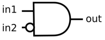
module top_module (
    input in1,
    input in2,
    output out);
    assign out=(~in2)&in1;
endmodule
48.Implement the following circuit:
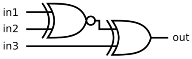
module top_module (
    input in1,
    input in2,
    input in3,
    output out);
    assign out=(in1~^in2)^in3;
endmodule
49.Ok, let's try building several logic gates at the same time. Build a combinational circuit with two inputs, a and b. There are 7 outputs, each with a logic gate driving it:
- out_and: a and b
- out_or: a or b
- out_xor: a xor b
- out_nand: a nand b
- out_nor: a nor b
- out_xnor: a xnor b
- out_anotb: a and-not b
module top_module(
    input a, b,
    output out_and,
    output out_or,
    output out_xor,
    output out_nand,
    output out_nor,
    output out_xnor,
    output out_anotb
);
    assign out_and = a&b;
    assign out_or = a|b;
    assign out_xor = a^b;
    assign out_nand = ~(a&b);
    assign out_nor = ~(a|b);
    assign out_xnor = a~^b;
    assign out_anotb = a&(~b);
endmodule
50.The 7400-series integrated circuits are a series of digital chips with a few gates each. The 7420 is a chip with two 4-input NAND gates.
Create a module with the same functionality as the 7420 chip. It has 8 inputs and 2 outputs.
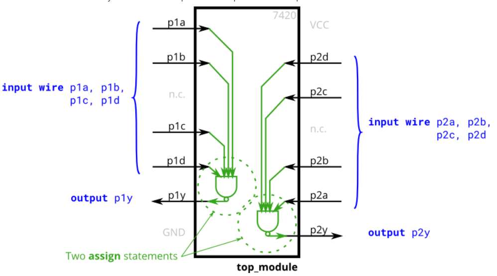
module top_module (
    input p1a, p1b, p1c, p1d,
    output p1y,
    input p2a, p2b, p2c, p2d,
    output p2y );
    assign p1y = ~(p1a&p1b&p1c&p1d);
    assign p2y = ~(p2a&p2b&p2c&p2d);
endmodule
51.Create a combinational circuit that implements the above truth table.

module top_module(
    input x3,
    input x2,
    input x1,  // three inputs
    output f   // one output
);
    assign f=~x3&x2|x1&x3;
endmodule
52.Create a circuit that has two 2-bit inputs A[1:0] and B[1:0], and produces an output z. The value of z should be 1 if A = B, otherwise z should be 0.
//运用同或
module top_module ( input [1:0] A, input [1:0] B, output z );
    wire [1:0] set;
    assign set=A~^B;
    assign z=set[0]&set[1];
endmodule
//assign 一句解决
module top_module ( input [1:0] A, input [1:0] B, output z );
    assign z=(A==B)?1:0;
endmodule
//if 语句
module top_module ( input [1:0] A, input [1:0] B, output z );
    always @(*)
        begin
            if(A == B)
                z = 1;
            else z = 0;
        end
endmodule
53.Module A is supposed to implement the function z = (x^y) & x. Implement this module.
module top_module (input x, input y, output z);
    assign z = (x^y) & x;
endmodule
54.Circuit B can be described by the following simulation waveform:

module top_module ( input x, input y, output z );
    assign z=x~^y;
endmodule
55.See mt2015_q4a and mt2015_q4b for the submodules used here. The top-level design consists of two instantiations each of subcircuits A and B, as shown below.
//就是上面两个例子。

module top_module (input x, input y, output z);
    wire z1,z2,z3,z4;
    A IA1 (x,y,z1);
    B IB1 (x,y,z2);
    A IA2 (x,y,z3);
    B IB2 (x,y,z4);
    assign z=(z1|z2)^(z3&z4);
endmodule

module A (input x, input y, output z);
    assign z = (x^y) & x;
endmodule

module B ( input x, input y, output z );
    assign z=x~^y;
endmodule
56.Suppose you are designing a circuit to control a cellphone's ringer and vibration motor. Whenever the phone needs to ring from an incoming call (input ring), your circuit must either turn on the ringer (output ringer = 1) or the motor (output motor = 1), but not both. If the phone is in vibrate mode (input vibrate_mode = 1), turn on the motor. Otherwise, turn on the ringer.
Try to use only assign statements, to see whether you can translate a problem description into a collection of logic gates.
Design hint: When designing circuits, one often has to think of the problem "backwards", starting from the outputs then working backwards towards the inputs. This is often the opposite of how one would think about a (sequential, imperative) programming problem, where one would look at the inputs first then decide on an action (or output). For sequential programs, one would often think "If (inputs are ___ ) then (output should be ___ )". On the other hand, hardware designers often think "The (output should be ___ ) when (inputs are ___ )".
The above problem description is written in an imperative form suitable for software programming (if ring then do this), so you must convert it to a more declarative form suitable for hardware implementation (assign ringer = ___). Being able to think in, and translate between, both styles is one of the most important skills needed for hardware design.
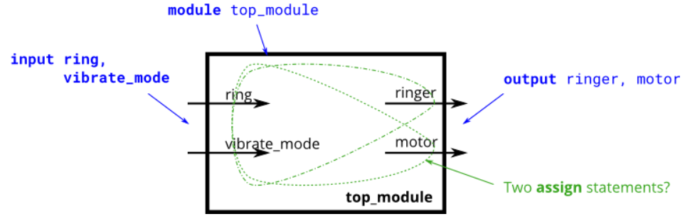
module top_module (
    input ring,
    input vibrate_mode,
    output ringer,       // Make sound
    output motor         // Vibrate
);
    assign ringer=ring&(~vibrate_mode);
    assign motor=ring&vibrate_mode;
endmodule
57.A heating/cooling thermostat controls both a heater (during winter) and an air conditioner (during summer). Implement a circuit that will turn on and off the heater, air conditioning, and blower fan as appropriate.
The thermostat can be in one of two modes: heating (mode = 1) and cooling (mode = 0). In heating mode, turn the heater on when it is too cold (too_cold = 1) but do not use the air conditioner. In cooling mode, turn the air conditioner on when it is too hot (too_hot = 1), but do not turn on the heater. When the heater or air conditioner are on, also turn on the fan to circulate the air. In addition, the user can also request the fan to turn on (fan_on = 1), even if the heater and air conditioner are off.
Try to use only assign statements, to see whether you can translate a problem description into a collection of logic gates.
module top_module (
    input too_cold,
    input too_hot,
    input mode,
    input fan_on,
    output heater,
    output aircon,
    output fan
);
    assign heater = mode & too_cold;
    assign aircon = ~mode & too_hot;
    assign fan = heater | aircon | fan_on;
endmodule
58.A "population count" circuit counts the number of '1's in an input vector. Build a population count circuit for a 3-bit input vector.
module top_module(
    input [2:0] in,
    output [1:0] out );
    assign out[1] = in[0]&in[1] | in[1]&in[2] | in[0]&in[2];
    assign out[0] = in[0] ^ in[1] ^ in[2];
endmodule
59.You are given a four-bit input vector in[3:0]. We want to know some relationships between each bit and its neighbour:
- out_both: Each bit of this output vector should indicate whether both the corresponding input bit and its neighbour to the left (higher index) are '1'. For example, out_both[2] should indicate if in[2] and in[3] are both 1. Since in[3] has no neighbour to the left, the answer is obvious so we don't need to know out_both[3].
- out_any: Each bit of this output vector should indicate whether any of the corresponding input bit and its neighbour to the right are '1'. For example, out_any[2] should indicate if either in[2] or in[1] are 1. Since in[0] has no neighbour to the right, the answer is obvious so we don't need to know out_any[0].
- out_different: Each bit of this output vector should indicate whether the corresponding input bit is different from its neighbour to the left. For example, out_different[2] should indicate if in[2] is different from in[3]. For this part, treat the vector as wrapping around, so in[3]'s neighbour to the left is in[0].
module top_module(
    input [3:0] in,
    output [2:0] out_both,
    output [3:1] out_any,
    output [3:0] out_different );
    assign out_both = {(in[2]&in[3]),(in[1]&in[2]),(in[0]&in[1])};
    assign out_any = {(in[2]|in[3]),(in[1]|in[2]),(in[0]|in[1])};
    assign out_different = {(in[0]^in[3]),(in[2]^in[3]),(in[2]^in[1]),(in[0]^in[1])};
endmodule
60.See also the shorter version: Gates and vectors.
You are given a 100-bit input vector in[99:0]. We want to know some relationships between each bit and its neighbour:
- out_both: Each bit of this output vector should indicate whether both the corresponding input bit and its neighbour to the left are '1'. For example, out_both[98] should indicate if in[98] and in[99] are both 1. Since in[99] has no neighbour to the left, the answer is obvious so we don't need to know out_both[99].
- out_any: Each bit of this output vector should indicate whether any of the corresponding input bit and its neighbour to the right are '1'. For example, out_any[2] should indicate if either in[2] or in[1] are 1. Since in[0] has no neighbour to the right, the answer is obvious so we don't need to know out_any[0].
- out_different: Each bit of this output vector should indicate whether the corresponding input bit is different from its neighbour to the left. For example, out_different[98] should indicate if in[98] is different from in[99]. For this part, treat the vector as wrapping around, so in[99]'s neighbour to the left is in[0].
module top_module(
    input [99:0] in,
    output [98:0] out_both,
    output [99:1] out_any,
    output [99:0] out_different );
    always@(*) begin
        for(integer i=0;i<99;i++) begin
            out_both[i]=in[i]&in[i+1];
        end
    end
    always@(*) begin
        for(integer j=1;j<100;j++) begin
            out_any[j]=in[j]|in[j-1];
        end
    end
    always@(*) begin
        for(integer k=0;k<99;k++) begin
            out_different[k]=in[k]^in[k+1];
        end
    end
    assign out_different[99]=in[99]^in[0];
endmodule
//答案采用的是移位计算法
module top_module(
    input [99:0] in,
    output [98:0] out_both,
    output [99:1] out_any,
    output [99:0] out_different );

    assign out_both = in[98:0] & in[99:1];
    assign out_any  = in[99:1] | in[98:0];
    assign out_different = in ^ {in[0],in[99:1]};
 //因为out_different要求一个wrapping且xor比较左边,故采用in[99:0] ^ {in[0], in[99:1]}
endmodule