目的主要是提取下TFT的电学模型,应用于Hspice的仿真。基于level61或level62或者verilog-A编辑的模型。
2020.04.06-----建个数据库:
utmost4 user Manuel:2.2 Creating a Database
On Windows, you can double-click on the SRDB shortcut to run the utility.
Now, connect to the database server using the following command:
login <servername>
This will prompt you for the database server password, which is initially set to 'simucad'.默认密码:“simucad”
Type 'simucad' and the prompt will change to:
SRDB <server_name> >
Use the following command to create a database.下面声明建立数据库。
create <my_database_name> ut4 <my_database_location>
这个<my_database_location>没有给具体信息,很抽象。但是有声明说最好是位于本机:“Silvaco recommends that the database location exists locally on the database server machine. This will reduce network traffic and speed up database access.”
示例:
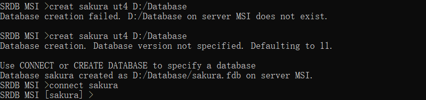
<my_database_location>是一个文件目录,而且还需要已有文件夹。
连接数据库,建立用户组:
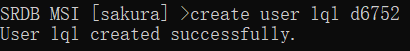
You will now need to create some Utmost IV users as follows. First connect to the newly created database and then add as many users as required.
connect <my_database_name>
create user <user_name> <password>
[注]密码不能全数字,否则会报错。
建立超级用户
In order to use the database manager tool described in Chapter 5 “Managing the Database”, you will need to set the superuser password as follows.
password superuser <superuser_password>
When you are finished, simply enter the command 'quit' to exit the SRDB application.
Now the software is installed, a database server is running, and a database and user are created.You are now ready to use the Utmost IV software.
全部设置完才能用Utmost.
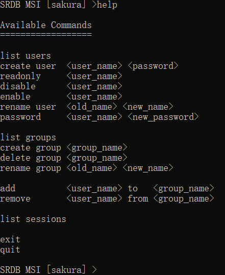
[注]SRDB User Manuel: At any prompt, type '?' or 'help' to get the current list of available commands or 'quit' to exit.
输入help会提示可用命令:1.原目录:
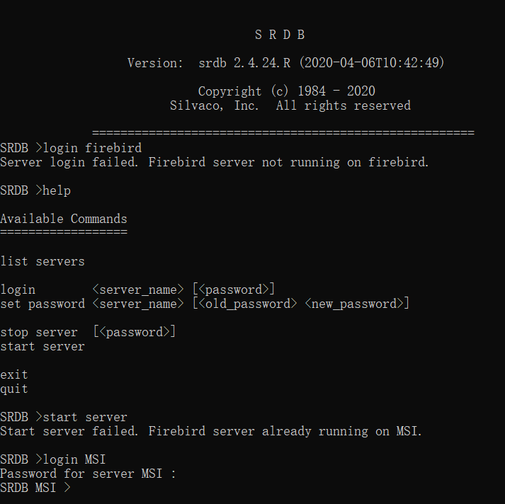
2.登入服务器后可用命令:
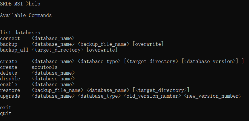
3.登入数据库后可用命令:
20.04.08----转入Utmost的使用
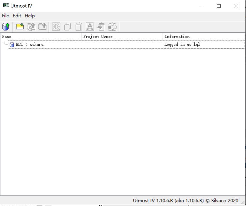
打开-找数据库-登入:
建立工程文件
Utmost4 user Manuel: 3.5 Creating a New Project
文件类型:Acquisition、Optimization (有啥区别?)
权限设置:略
Utmost4 user Manuel:Chapter 6 Acquisition Module 新建了Acquisition文件
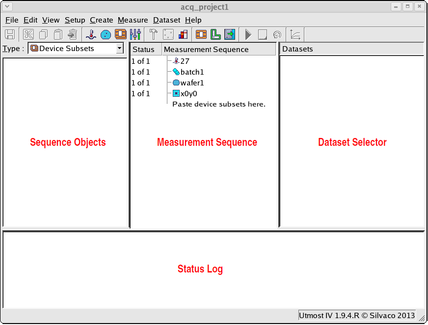
6.1 Defining Temperatures
一般默认27度
6.2 Defining the Wafer Map (不知道有啥意义)
The wafer map is where you define the physical location of the devices for which you intend to acquire datasets.
6.2.1 Defining the Header, Batch and Wafer Information
6.2.2 Defining the Die Selection
6.2.3 Defining the Group Selection
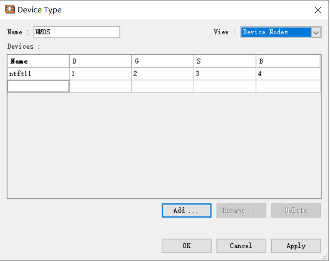
6.3 Defining Devices(器件设置)
Setup-Devices: to create, edit, or delete a device type.
器件的设置分为:Device Attributes, the Device Nodes, and the Netlist Text.即器件属性、器件节点和网表。
器件属性:
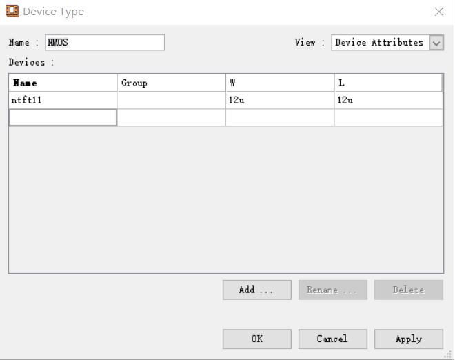
名称、组以及器件沟道宽长。
器件节点:
网表,与节点相关,具体应与Hspice语法相似:

6.4 Defining Extractions:存疑,7.7 Defining Extractions
6.5 Defining Variables:定义变量,但是变量的意义及具体设置仍存疑。
6.6 Defining Hardware:应该是测量设备的定义,但是可能因为之前的设置不全,暂时点不了。
6.7 Defining Connections:跟上面一起设置。
6.8 The Model Library:模型库,Full details on the model libary window are given in Section 7.6 “The Model Library”.
新建模型卡:
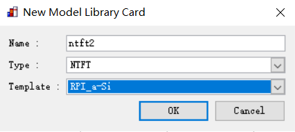
NTFT有三个Template:非晶硅、多晶硅还有UOTFT(??)对应的是level=35,36和37。选定非晶硅模型,设置后的模型卡如下:
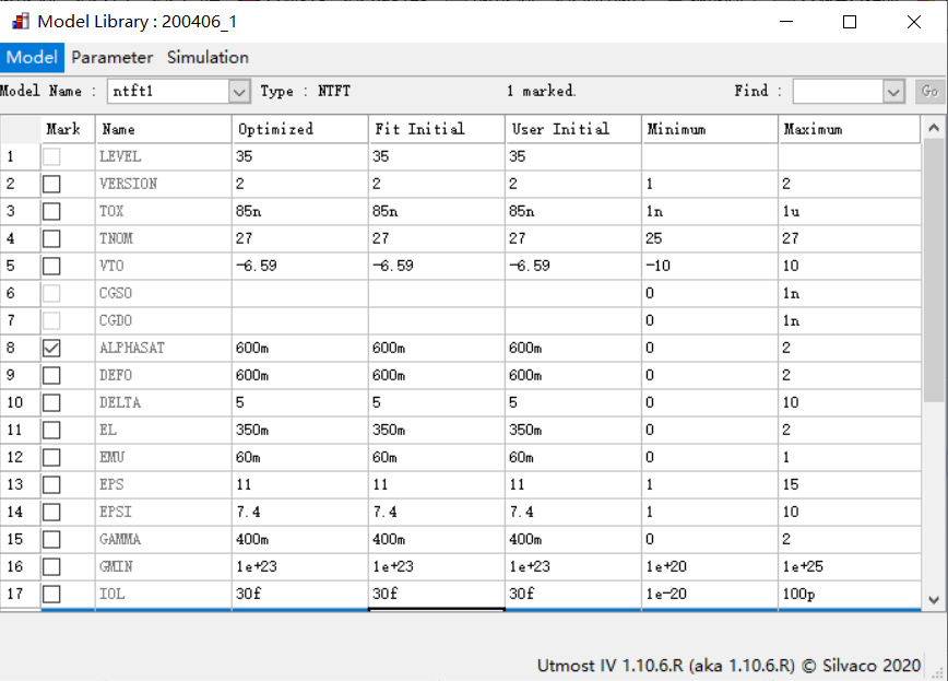
列头分别是Name、Optimized、Fit Initial、User Initial、Minimum、Maximum.
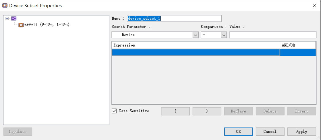
6.9 The Device Subset:设备子集设置,存疑
6.10 The Measurement Setup:
6.11 The Extraction Setup:Full details on this are given in Section 7.15 “The Extraction Setup”.
6.12 Acquiring Data using the Measurement Sequence:???
6.13 The Measured Datasets:运行测量序列后,将使用仪器或模拟生成数据集,并将其存储在数据库中。
Utmost的手册到后面就基本看不懂了...晚上再看下其他资料。