实验任务一:虚连接的配置
-
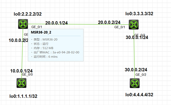
建立物理连接
-
配置ospf协议
RTA G0/0 lo0加入area0,使能接口。
RTB G0/0 加入area0,G0/1.lo0加入area1,使能接口
RTC G0/2 加入area2,G0/1.lo0加入area1,使能接口
RTD G0/2 ,lo0加入area2,使能接口.
[RTD]display ip routing-table
Destinations : 13 Routes : 13
Destination/Mask Proto Pre Cost NextHop Interface
0.0.0.0/32 Direct 0 0 127.0.0.1 InLoop0
4.4.4.4/32 Direct 0 0 127.0.0.1 InLoop0
30.0.0.0/24 Direct 0 0 30.0.0.2 GE0/2
30.0.0.0/32 Direct 0 0 30.0.0.2 GE0/2
30.0.0.2/32 Direct 0 0 127.0.0.1 InLoop0
30.0.0.255/32 Direct 0 0 30.0.0.2 GE0/2
127.0.0.0/8 Direct 0 0 127.0.0.1 InLoop0
127.0.0.0/32 Direct 0 0 127.0.0.1 InLoop0
127.0.0.1/32 Direct 0 0 127.0.0.1 InLoop0
127.255.255.255/32 Direct 0 0 127.0.0.1 InLoop0
224.0.0.0/4 Direct 0 0 0.0.0.0 NULL0
224.0.0.0/24 Direct 0 0 0.0.0.0 NULL0
255.255.255.255/32 Direct 0 0 127.0.0.1 InLoop0
3.配置虚连接
[RTB-ospf-1-area-0.0.0.1]vlink-peer 3.3.3.3
[RTC-ospf-1-area-0.0.0.1]vlink-peer 2.2.2.2
查看RTC的邻居表
[RTC-ospf-1-area-0.0.0.1]display ospf peer
     OSPF Process 1 with Router ID 3.3.3.3
           Neighbor Brief Information
Area: 0.0.0.1
Router ID Address Pri Dead-Time State Interface
2.2.2.2 20.0.0.1 1 34 Full/DR GE0/1
Area: 0.0.0.2
Router ID Address Pri Dead-Time State Interface
4.4.4.4 30.0.0.2 1 34 Full/BDR GE0/2
Virtual link:
Router ID Address Pri Dead-Time State Interface
2.2.2.2 20.0.0.1 1 30 Full GE0/1
[RTC]display ospf vlink
     OSPF Process 1 with Router ID 3.3.3.3
             Virtual Links
Virtual-link Neighbor-ID -> 2.2.2.2, Neighbor-State: Full//邻居状态
Interface: 20.0.0.2 (GigabitEthernet0/1)
Cost: 1 State: P-2-P Type: Virtual
Transit Area: 0.0.0.1
Timers: Hello 10, Dead 40, Retransmit 5, Transmit Delay 1
MTID Cost Disabled Topology name
0 1 No base
[RTD]display ip routing-table
Destinations : 18 Routes : 18
Destination/Mask Proto Pre Cost NextHop Interface
0.0.0.0/32 Direct 0 0 127.0.0.1 InLoop0
1.1.1.1/32 O_INTER 10 3 30.0.0.1 GE0/2
2.2.2.2/32 O_INTER 10 2 30.0.0.1 GE0/2
3.3.3.3/32 O_INTER 10 1 30.0.0.1 GE0/2
4.4.4.4/32 Direct 0 0 127.0.0.1 InLoop0
10.0.0.0/24 O_INTER 10 3 30.0.0.1 GE0/2
20.0.0.0/24 O_INTER 10 2 30.0.0.1 GE0/2
30.0.0.0/24 Direct 0 0 30.0.0.2 GE0/2
30.0.0.0/32 Direct 0 0 30.0.0.2 GE0/2
30.0.0.2/32 Direct 0 0 127.0.0.1 InLoop0
30.0.0.255/32 Direct 0 0 30.0.0.2 GE0/2
127.0.0.0/8 Direct 0 0 127.0.0.1 InLoop0
127.0.0.0/32 Direct 0 0 127.0.0.1 InLoop0
127.0.0.1/32 Direct 0 0 127.0.0.1 InLoop0
127.255.255.255/32 Direct 0 0 127.0.0.1 InLoop0
224.0.0.0/4 Direct 0 0 0.0.0.0 NULL0
224.0.0.0/24 Direct 0 0 0.0.0.0 NULL0
255.255.255.255/32 Direct 0 0 127.0.0.1 InLoop0
实验任务二:验证的配置
-
在RTB配置接口验证
[RTB-GigabitEthernet0/0]ospf authentication-mode simple plain 123
[RTB-GigabitEthernet0/0]display ospf peerOSPF Process 1 with Router ID 2.2.2.2 Neighbor Brief Information
Area: 0.0.0.1
Router ID Address Pri Dead-Time State Interface
3.3.3.3 20.0.0.2 1 39 Full/BDR GE0/1
Virtual link:
Router ID Address Pri Dead-Time State Interface
3.3.3.3 20.0.0.2 1 31 Full GE0/1
2.在RTA配置接口验证
[RTA-GigabitEthernet0/0]ospf authentication-mode simple plain 123
[RTA-GigabitEthernet0/0]display ospf peer
  OSPF Process 1 with Router ID 2.2.2.2
        Neighbor Brief Information
Area: 0.0.0.0
Router ID Address Pri Dead-Time State Interface
1.1.1.1 10.0.0.1 1 38 Full/BDR GE0/0
Area: 0.0.0.1
Router ID Address Pri Dead-Time State Interface
3.3.3.3 20.0.0.2 1 36 Full/BDR GE0/1
Virtual link:
Router ID Address Pri Dead-Time State Interface
3.3.3.3 20.0.0.2 1 38 Full GE0/1
验证1:ospf接口配置验证和区域验证
-
在RTA配置接口验证,RTB配置区域验证
[RTB-GigabitEthernet0/0]ospf authentication-mode simple plain 123
[RTA-ospf-1-area-0.0.0.0]authentication-mode simple plain 123
查看RTB的邻居表
[RTB-ospf-1]display ospf peerOSPF Process 1 with Router ID 2.2.2.2 Neighbor Brief Information
Area: 0.0.0.0
Router ID Address Pri Dead-Time State Interface
1.1.1.1 10.0.0.1 1 36 Full/BDR GE0/0
Area: 0.0.0.1
Router ID Address Pri Dead-Time State Interface
3.3.3.3 20.0.0.2 1 40 Full/BDR GE0/1
Virtual link:
Router ID Address Pri Dead-Time State Interface
3.3.3.3 20.0.0.2 1 32 Full GE0/1
此时RTA和RTB建立邻居成功。
3.在RTB上配置区域验证
[RTB-ospf-1-area-0.0.0.0]authentication-mode simple plain 456
查看RTB的邻居
[RTB-ospf-1]display ospf peer
     OSPF Process 1 with Router ID 2.2.2.2
           Neighbor Brief Information
Area: 0.0.0.0
Router ID Address Pri Dead-Time State Interface
1.1.1.1 10.0.0.1 1 36 Full/BDR GE0/0
Area: 0.0.0.1
Router ID Address Pri Dead-Time State Interface
3.3.3.3 20.0.0.2 1 40 Full/BDR GE0/1
Virtual link:
Router ID Address Pri Dead-Time State Interface
3.3.3.3 20.0.0.2 1 32 Full GE0/1
发现RTA和RTB还是能够建立邻居
说明即使区域验证密码不通过,只要接口密码通过一样可以建立邻居。
补充:
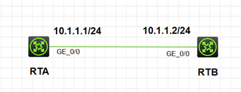
1.RTA、RTB配置相同的区域验证
[RTA-ospf-1-area-0.0.0.0]authentication-mode simple plain 123
[RTB-ospf-1-area-0.0.0.0]authentication-mode simple plain 123
[RTB]display ospf peer
     OSPF Process 1 with Router ID 10.1.1.2
           Neighbor Brief Information
Area: 0.0.0.0
Router ID Address Pri Dead-Time State Interface
10.1.1.1 10.1.1.1 1 33 Full/DROther GE0/0
2.RTB配置接口验证
[RTB -GigabitEthernet0/0]ospf authentication-mode simple plain 456
发现接口验证不一样,区域验证相同也无法建立邻居。