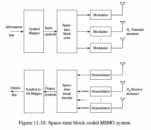
At the transmitter, the sequence of information bits is fed into a symbol mapper that maps a block of
bits into signal points {sd selected from a signal constellation such as PAM, PSK, or
QAM, consisting of M = 2^b signal points. These signal points are fed as a block to
a space-time encoder that maps the information symbols to a parallel set of identical
modulators. In turn, the modulators map the signal points into corresponding waveforms
that are transmitted simultaneously on the Nr antennas. Below, we describe two
types of space-time codes: block codes and trellis codes.
Space-Time Block Codes
A space-time block code (STBC) is defined by a generator matrix G, having N rows
and Nr columns, of the form
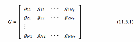
in which the elements {gij} are signal points resulting from a mapping of information
bits to corresponding signal points from a binary or M-ary signal constellation. By
employing Ny transmit antennas, each row of G may contain up to Ny different signal
points (symbols), which are transmitted on the Ny antennas in a time slot. Thus, the
first row of symbols in G is transmitted on the Ny antennas in the first time slot, the
second row of symbols in G is transmitted on the Ny antennas in the second time slot,
and the Nth row of symbols in G is transmitted on the Ny antennas in the Nth time slot.
Therefore, N time slots are used to transmit the symbols in the N rows of the generator
matrix G. The ratio of the number of different symbols transmitted to the number of
time slots is called the spatial code rate Rs = Nt / N.
In the design of the generator matrix of a STBC, it is desirable to focus on three
principal objectives: (1) achieving the highest possible diversity of NyNR, (2) achieving
the highest possible (throughput) rate, and (3) minimizing the complexity of the
decoder.
Space-Time Trellis Codes
Space-time trellis codes (STTCs) are similar to trellis codes in trellis-coded modulation
(TCM) in that they are formed by combining a trellis code with an appropriately
selected signal constellation with the objective of achieving a coding gain. In the case
of a space-time code, the primary objective is to achieve the largest possible spatial
diversity at the highest coding rate.
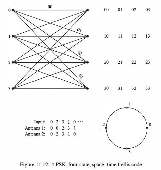
As an example of a STTC, we consider the four-state trellis code shown in
Figure 11.12, which is designed for two transmit antennas and QPSK modulation.
The states are denoted as St = 0, 1, 2, 3. The input to the encoder is a pair of bits
(00, 01, 10, 11) that are mapped into the corresponding phases, which are numbered
(0, 1, 2, 3), respectively. The indices 0, 1, 2, 3 correspond to the four phases, which are
called symbols. Initially, the encoder is in state St = 0. Then, for each pair of input
bits that are mapped into a corresponding symbol, the encoder generates a pair of symbols,
the first of which is transmitted on the first antenna and the second of which is
transmitted simultaneously on the second antenna. For example, when the encoder is
in state St = 0 and the input bits are 11, the symbol is a 3. The STTC outputs the pair
of symbols ( 0, 3) , corresponding to the phases 0 and 3 TT I 2. The zero phase signal is
transmitted in the first antenna and the 3 rr / 2 phase signal is transmitted on the second
antenna. At this point the encoder goes to state St = 3. If the next two input bits are
01, the encoder outputs the symbols (3, 1), which are transmitted on the two antennas.
Then the encoder goes to state St = 1, and this procedure continues. At the end of a
block of input bits, say a frame of data, zeros are inserted in the data stream to return
the encoder to the state St = 0. Thus the STTC transmits at a bit rate of 2 bps/Hz.
Matlab Simulation code
 1 % MATLAB script for Space-Time Treills Code
 2
 3 echo off
 4 no_bits = 10;                   % Determine the length of input vector
 5 input = randi([0 3],1,no_bits); % Define the input as a random vector
 6 if mod(no_bits,2) ~= 0
 7     input = [input 0];
 8 end
 9 L = size(input,2);
10 st_0 = 0;                       % Initial state
11 st_c = st_0;                    % Initialization of the current state
12 ant_1 = [];                     % Output of antenna 1
13 ant_2 = [];                     % Output of antenna 2

14 % Update the current state as well as outputs of antennas 1 and 2:
15 for i = 1:L
16     st_p = st_c;
17     if input(i) == 0
18         st_c = 0;
19     elseif input(i) == 1
20         st_c = 1;
21     elseif input(i) == 2
22         st_c = 2;
23     else
24         st_c = 3;
25     end
26     ant_1 = [ant_1 st_p];
27     ant_2 = [ant_2 st_c];
28 end

29 if st_c ~= 0
30     st_p = st_c;
31     st_c = 0;
32     ant_1 = [ant_1 st_p];
33     ant_2 = [ant_2 st_c];
34 end

35 % Display the input vector and outputs of antennas 1 and 2:
36 disp(['The input sequence is:                      ', num2str(input)])
37 disp(['The transmitted sequence by antenna 1 is:   ', num2str(ant_1)])
38 disp(['The transmitted sequence by antenna 2 is:   ', num2str(ant_2)])


output,
The input sequence is: 3 2 1 0 2 3 1 3 2 1
The transmitted sequence by antenna 1 is: 0 3 2 1 0 2 3 1 3 2 1
The transmitted sequence by antenna 2 is: 3 2 1 0 2 3 1 3 2 1 0
Reference,
1. <<Contemporary Communication System using MATLAB>> - John G. Proakis