Introduction
This example shows how to generate a time domain waveform containing a Physical Downlink Shared Channel (PDSCH), corresponding Physical Downlink Control Channel (PDCCH) transmission and the Physical Control Format Indicator Channel (PCFICH), for one subframe.
-
Physical Downlink Shared Channel (PDSCH)
-
Physical Downlink Control Channel (PDCCH)
-
Physical Downlink Control Format Indicator Channel (PCFICH)
Cell-wide Settings
enb.NDLRB = 6;                % No of Downlink Resource Blocks(DL-RB)
enb.CyclicPrefix = 'Normal';  % CP length
enb.PHICHDuration = 'Normal'; % Normal PHICH duration
enb.DuplexMode = 'FDD';       % FDD duplex mode
enb.CFI = 3;                  % 4 PDCCH symbols
enb.Ng = 'Sixth';             % HICH groups
enb.CellRefP = 4;             % 4-antenna ports
enb.NCellID = 10;             % Cell id
enb.NSubframe = 0;            % Subframe number 0
Subframe Resource Grid Generation
Creating an empty resource grid for one subframe. The subframe is a 3 dimensional matrix. The number of rows represents the number of subcarriers available, this is equal to 12*enb.NDLRB since there are 12 subcarriers per resource block. The number of columns equals the number of OFDM symbols in a subframe, i.e. 7*2, since we have 7 OFDM symbols per slot for normal cyclic prefix and there are 2 slots in a subframe. The number of planes (3rd dimension) in subframe is 4 corresponding to the 4 antenna ports as specified in enb.CellRefP.

DL-SCH and PDSCH Settings
The DL-SCH and PDSCH are configured using a structure pdsch. The settings here configure 4 antenna transmit diversity with QPSK modulation.
pdsch.NLayers = 4;                       % No of layers
pdsch.TxScheme = 'TxDiversity';          % Transmission scheme
pdsch.Modulation = 'QPSK';               % Modulation scheme
pdsch.RNTI = 1;                          % 16-bit UE-specific mask
pdsch.RV = 0;                            % Redundancy Version
DL-SCH Channel Coding
Now generate the DL-SCH bits and apply channel coding. This includes CRC calculation, code block segmentation and CRC insertion, turbo coding, rate matching and code block concatenation.
The DL-SCH transport block size is chosen according to rules in TS36.101, Annex A.2.1.2 "Determination of payload size" with target code rate  and number of bits per subframe given by
 codedTrBlkSize.
codedTrBlkSize = pdschInfo.G;          % Available PDSCH bits

transportBlkSize = 152;                % Transport block size
dlschTransportBlk = randi([0 1], transportBlkSize, 1);

% Perform Channel Coding
codedTrBlock = lteDLSCH(enb, pdsch, codedTrBlkSize, dlschTransportBlk);
PDSCH Complex Symbols Generation
The following operations are applied to the coded transport block to generate the Physical Downlink Shared Channel complex symbols: scrambling, modulation, layer mapping and precoding. This can be achieved using ltePDSCH. As well as some of the cell-wide settings specified in enb this function also requires other parameters related to the modulation and channel transmission configuration, pdsch. The resulting matrix pdschSymbols has 4 columns. Each column contains the complex symbols to map to each antenna port.
pdschSymbols = ltePDSCH(enb, pdsch, codedTrBlock);
PDSCH Mapping
The complex PDSCH symbols are then easily mapped to each of the resource grids for each antenna port using a simple assignment operation. The locations of the PDSCH symbols in the resource grids are given by pdschIndices.
% Map PDSCH symbols on resource grid
subframe(pdschIndices) = pdschSymbols;
DCI Message Configuration
Downlink Control Information (DCI), conveys information about the DL-SCH resource allocation, transport format, and information related to the DL-SCH hybrid ARQ. lteDCI can be used to generate a DCI message to be mapped to the Physical Downlink Control Channel (PDCCH). These parameters include the number of downlink Resource Blocks (RBs), the DCI format and the Resource Indication Value (RIV). The RIV of 26 correspond to full bandwidth assignment.
DCI Channel Coding
The DCI message bits are channel coded. This includes the following operations: CRC insertion, tail-biting convolutional coding and rate matching. The field PDCCHFormat indicates that one Control Channel Element (CCE) is used for the transmission of PDCCH, where a CCE is composed of 36 useful resource elements.
PDCCH Bits Generation
The capacity of the control region depends on the bandwidth, the Control Format Indicator (CFI), the number of antenna ports and the PHICH groups. The total number of resources available for PDCCH can be calculated using ltePDCCHInfo.
pdcchInfo = ltePDCCHInfo(enb);    % Get the total resources for PDCCH
pdcchBits = -1*ones(pdcchInfo.MTot, 1); % Initialized with -1

% Performing search space for UE-specific control channel candidates
candidates = ltePDCCHSpace(enb, pdcch, {'bits','1based'});

% Mapping PDCCH payload on available UE-specific candidate. In this example
% the first available candidate is used to map the coded DCI bits.
pdcchBits( candidates(1, 1) : candidates(1, 2) ) = codedDciBits;
PDCCH Complex Symbol Generation
From the set of bits used in pdcchBits (values not set to -1) PDCCH complex symbols are generated. The following operations are required: scrambling, QPSK modulation, layer mapping and precoding.
ltePDCCH takes a set of PDCCH bits and generates complex-valued PDCCH symbols performing the operations mentioned above. In this case pdcchSymbols is a 4 column matrix, each corresponding to each antenna port.
pdcchSymbols = ltePDCCH(enb, pdcchBits);
CFI Channel Coding
The number of OFDM symbols in a subframe is linked to the Control Format Indicator (CFI) value. Cell-wide settings structure enb specifies a CFI value of 3, which means that 4 OFDM symbols are used for the control region in the case of 6 downlink resource blocks. The CFI is channel coded using lteCFI. The resulting set of coded bits is a 32 element vector.
cfiBits = lteCFI(enb);
PCFICH Complex Symbol Generation
The CFI coded bits are then scrambled, QPSK modulated, mapped to layers and precoded to form the PCFICH complex symbols. The pcfichSymbols is a matrix having 4 columns where each column contains the PCFICH complex symbols that map to each of the antenna ports.
pcfichSymbols = ltePCFICH(enb, cfiBits);
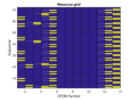
Plot Grid
Plot the resource grid for the first antenna. This includes (in yellow) the physical channels added in the example: PDSCH, PDCCH and PCFICH.
Reference
1. TS 36.101
2. MathWorks