Introduction
This page describes how to test the features of the SAMA5D2-compatible ADC device. This driver uses the Industrial Input/Output (IIO) subsystem.
Documentation for the IIO subsystem is available in the kernel source code directory: drivers/staging/iio/Documentation![]() and Documentation/iio
and Documentation/iio![]() .
.
Kernel
The driver (features are added little by little) for the SAMA5D2-compatible ADC device is available on:
- linux-4.1-at91

- linux-4.4-at91
- Mainline kernel from version 4.6
The ADC drivers is automatically selected if you use sama5_defconfig. Otherwise, check you have set CONFIG_AT91_SAMA5D2_ADC.
To check that ADC driver is correclty loaded:
# dmesg|grep at91-sama5d2_adc
at91-sama5d2_adc fc030000.adc: version: 800
# ls /sys/bus/iio/devices/iio:device0
dev                         in_voltage2_raw           in_voltage8_raw
in_voltage-voltage_scale    in_voltage3_raw           in_voltage9_raw
in_voltage0-voltage1_raw    in_voltage4-voltage5_raw  in_voltage_scale
in_voltage0_raw             in_voltage4_raw           name
in_voltage10-voltage11_raw  in_voltage5_raw           of_node
in_voltage10_raw            in_voltage6-voltage7_raw  power
in_voltage11_raw            in_voltage6_raw           sampling_frequency
in_voltage1_raw             in_voltage7_raw           subsystem
in_voltage2-voltage3_raw    in_voltage8-voltage9_raw  uevent
![]() Tips: The ADC controller doesn't manage its pins in the same way as other ones. PIOs can't be assigned to it. It will automatically use them (if not assigned to another peripheral) when enabling the corresponding channel. To reserve PIOs for the ADC, you could declare them as GPIO in the device tree. By doing this, if there is a conflict with another peripheral, you'll be warned. You should also disable pull-up and pull-down to have coherent measurement when the PIO is not used by the ADC device. Here is an exemple from at91-sama5d2_xplained.dts for AD4 signal:
Tips: The ADC controller doesn't manage its pins in the same way as other ones. PIOs can't be assigned to it. It will automatically use them (if not assigned to another peripheral) when enabling the corresponding channel. To reserve PIOs for the ADC, you could declare them as GPIO in the device tree. By doing this, if there is a conflict with another peripheral, you'll be warned. You should also disable pull-up and pull-down to have coherent measurement when the PIO is not used by the ADC device. Here is an exemple from at91-sama5d2_xplained.dts for AD4 signal:
pinctrl_adc_default: adc_default {
        pinmux = <PIN_PD23__GPIO>;
        bias-disable;
};
Software triggers
Unsigned single-ended channel conversion
Setup
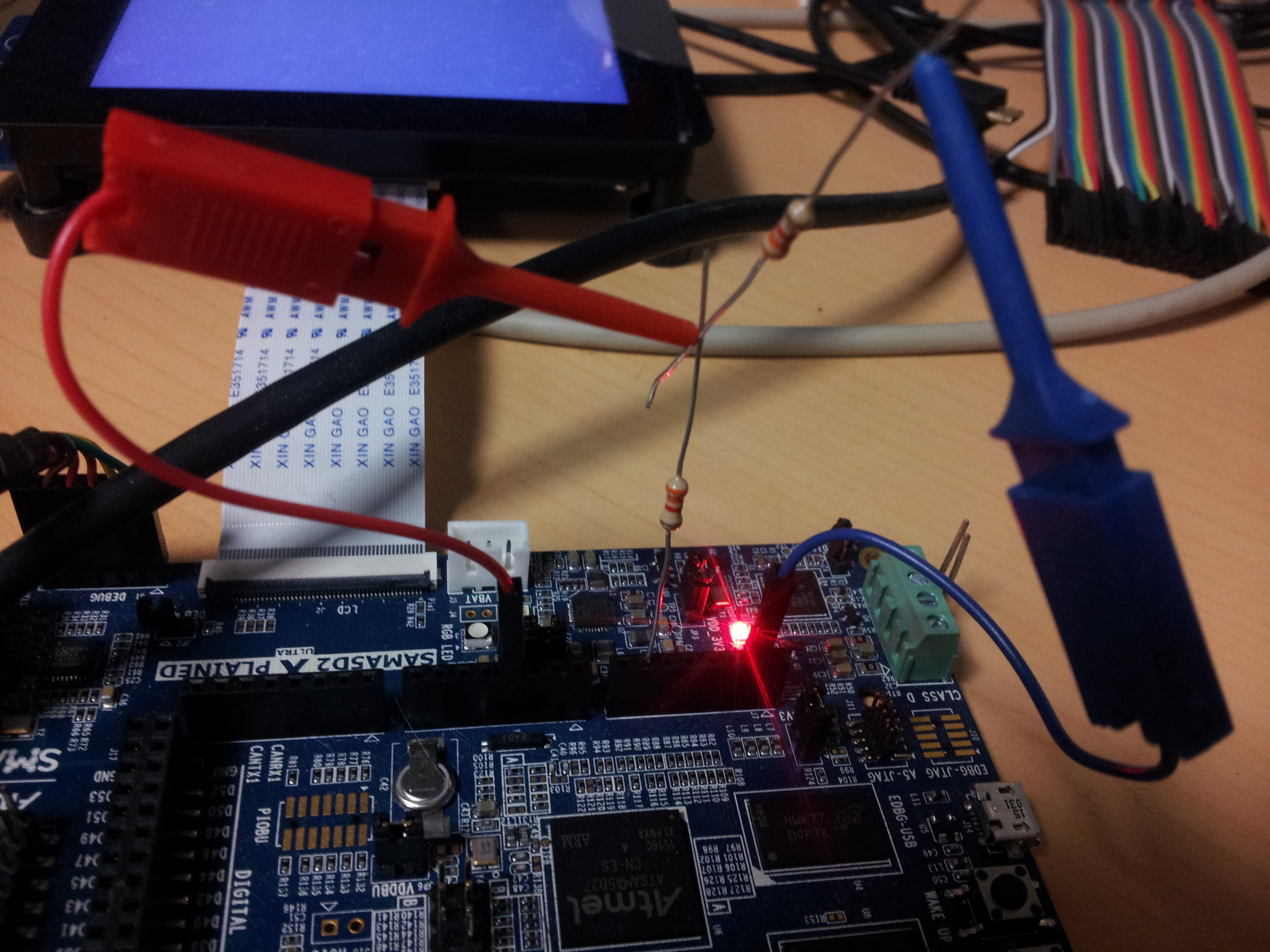
- Connect a waveform or DC generator to the pin 4 of J8 connector called A3. You can also use a resistor bridge as the image below shows
Test procedure
- request the conversion:
# cat /sys/bus/iio/devices/iio:device0/in_voltage4_raw
3693
- request the scale:
# cat /sys/bus/iio/devices/iio:device0/in_voltage_scale
0.805664062
- check the conversion by multiplying the conversion value with the scale:
3693 x 0.8 = 2954.4 mV
Signed differential channel conversion
Setup
Use A3 (AD4) and A6 (AD5) from J8 connector
Test procedure
- request the conversion:
# cat /sys/bus/iio/devices/iio:device0/ in_voltage4-voltage5_raw
-396
- request the scale:
# cat /sys/bus/iio/devices/iio:device0/in_voltage-voltage_scale
1.611328125
- check the conversion by multiplying the conversion value with the scale:
-396 x 1.6 = -633,6 mV
- you can compare it manually with the help of single ended conversions:
# cat /sys/bus/iio/devices/iio:device0/in_voltage4_raw
1237
# cat /sys/bus/iio/devices/iio:device0/in_voltage5_raw
2031
# cat /sys/bus/iio/devices/iio:device0/in_voltage_scale
0.805664062
(1237-2031) x 0.8 = -635.2 mV