连接
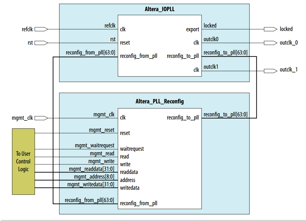
Avalon -MM接口
mgmt_waitrequest:当 PLL 重配置进程开始后,此端口变高并在 PLL 重配置期间保持高电平。
PLL 重配置进程完成后,此端口变低。
I/O PLL重配写操作步骤:
1、 为mgmt_address和mgmt_writedata设置有效值,并且使能mgmt_write一个mgmt_clk周期
2、 重复步骤1共8次
3、 为mgmt_address设置启动地址9’b000000000,mgmt._writedata任意,并且使能mgmt_write一个mgmt_clk周期
4、 当配置完成后mgmt_waitrequest拉低
注:(1)如果发送的命令超过8个,内部的FIFO会溢出。
(2)每个命令(地址数据对)属于以下三种之一:
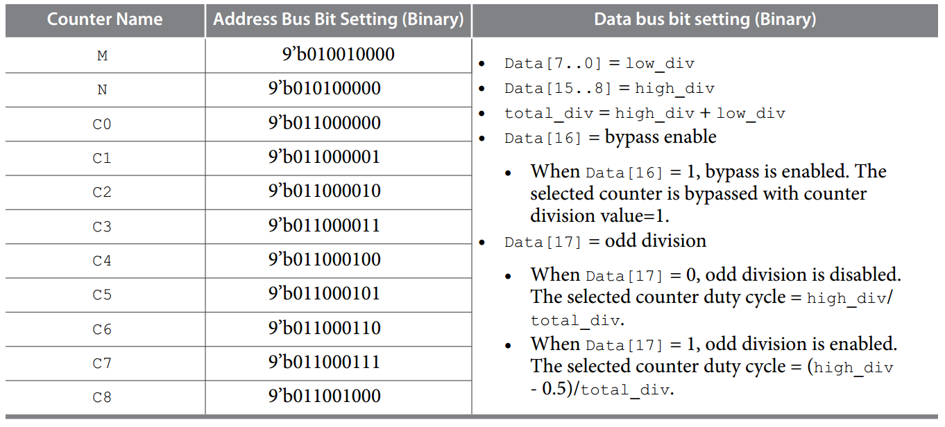
1、计数器重配设置
2、带宽重配设置
3、动态相位移动
1、计数器重配设置寄存器
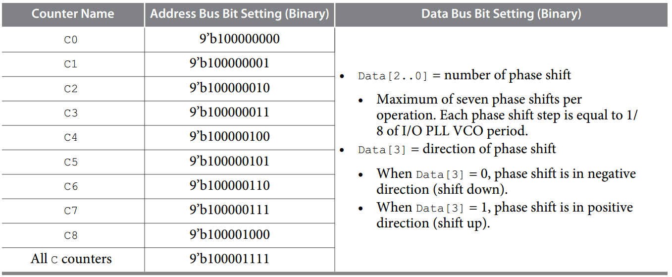
1、 动态相位移动
3、带宽重配设置
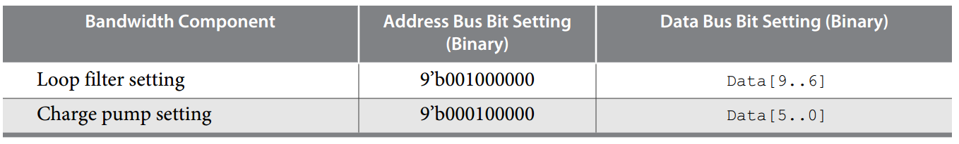
环路滤波器和充电泵设置
CP :Charge pump setting
BP :Loop filter setting
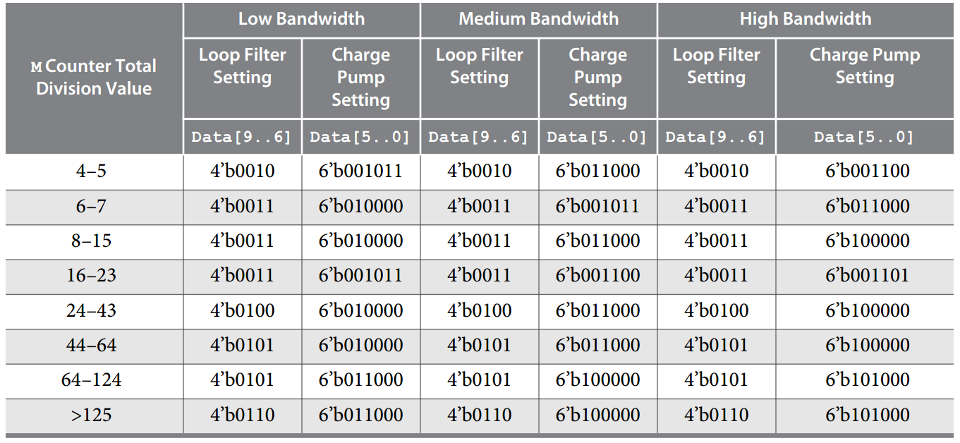
对于PLL的带宽选择有三种—在PLL的参数设置中可以选择,它们是Low,Medium和High。可以来看下手册上对它们的说明:
• Low—PLL with a low bandwidth has better jitter rejection but a slower lock time.
• High—PLL with a high bandwidth has a faster lock time but tracks more jitter.
• Medium—A medium bandwidth offers a balance between lock time and jitter rejection.
带宽应该指的是环路滤波带宽,带宽越小就越不容易锁定,太宽了时钟抖动会比较大。
VCO的设置范围为600~1434M
其中M,N,C的参数分别对应上面,C0表示输出通道0,C1表示输出通道1,以此类推。
module mr_reconfig_master_pll #(
parameter MIF_OFFSET = 7, // total cram address that differ resulted from PLL mif files comparison
parameter ADDR_WIDTH_FOR_VALUEMASK = 6, // number of bits representation for total ROM depth for PLL valuemask
parameter ADDR_WIDTH_FOR_DPRIOADDR = 3, // number of bits representation for total CRAM address that differ
parameter DPRIO_ADDRESS_WIDTH = 9, //
parameter DPRIO_DATA_WIDTH = 32 //
) (
input wire clock,
input wire reset,
input wire reconfig_request, // from main state machine - request for reconfig
output reg reconfig_done, // to main state machine - indicate reconfig is completed
input wire clr_reconfig_done, // from main state machine - full handshake signal to acknowledge reconfig_done (both rx & pll) is serviced
input wire [ADDR_WIDTH_FOR_VALUEMASK-1:0] offset_pointer, // from main state machine - indicate which rom address (mif range) to be read
output wire [ADDR_WIDTH_FOR_VALUEMASK-1:0] valuemask_addr_ptr, // to value mask rom - start from offset_pointer & increment by 1 for each cycle & increment for MIF_OFFSET times
output wire [ADDR_WIDTH_FOR_DPRIOADDR-1:0] dprioaddr_addr_ptr, // to dprio addr rom - start from 0 & increment by 1 for each cycle & increment for MIF_OFFSET times
input wire [7:0] dprio_offset, // from dprio addr rom - indicate which cram address to write to
input wire [31:0] field_valuemask, // from value mask rom - indicate the value of cram bit to write to (in 8-bitmask format)
input wire reconfig_waitrequest, //
output reg reconfig_write, // Reconfig signals to/from PLL reconfig controller
output reg [DPRIO_ADDRESS_WIDTH-1:0] reconfig_address, //
output reg [DPRIO_DATA_WIDTH-1:0] reconfig_writedata //
);
localparam [2:0]
IDLE = 0,
MOD = 1,
WR = 2,
TRANS = 3,
START = 4,
WAITREQUEST = 5,
DONE = 6;
reg [2:0] next_state;
reg [2:0] current_state;
wire [DPRIO_DATA_WIDTH-1:0] data_to_write; // data to be written to PLL
reg [ADDR_WIDTH_FOR_DPRIOADDR-1:0] num_exec; // offset start from 0 & increment by 1 & for MIF_OFFSET times
reg [ADDR_WIDTH_FOR_VALUEMASK-1:0] pointer; // get the pointer start offset from main state machine
reg last_offset; // indicate if the current offset is the last or not
wire reconfig_waitrequest_sync; // synchronize waitrequest signal from the PLL reconfig controller
altera_std_synchronizer #(.depth(3)) u_reconfig_waitrequest_sync (.clk(clock),.reset_n(1'b1),.din(reconfig_waitrequest),.dout(reconfig_waitrequest_sync));
always @ (posedge clock or posedge reset)
begin
if (reset) begin
current_state <= IDLE;
end else begin
current_state <= next_state;
end
end
always @ (*)
begin
next_state = current_state;
case (current_state)
IDLE: begin
if (reconfig_request) begin //由主状态机发出重配请求
next_state = MOD;
end
end
MOD: begin
next_state = WR;
end
// reconfig write
WR: begin
if (~reconfig_request) begin//如果重配请求清除则返回IDLE状态
next_state = IDLE;
end else begin
next_state = TRANS;
end
end
// cycle to next offset before it hits MIF_OFFSET times
//TRANS state:
TRANS: begin
if (last_offset) begin
next_state = START;
end else begin
next_state = MOD;
end
end
// write to start register to initiate the PLL reconfig
// then wait for waitrequest signal to be asserted
//发送启动地址0x000
START: begin
if (reconfig_waitrequest_sync) begin
next_state = WAITREQUEST;
end else if (~reconfig_request) begin
next_state = IDLE;
end
end
// once waitrequest is deasserted, PLL reconfig is complete
//等待PLL重配完成
WAITREQUEST: begin
if (~reconfig_waitrequest_sync) begin
next_state = DONE;
end else if (~reconfig_request) begin
next_state = IDLE;
end
end
// full handshaking between this master and main state machine
DONE: begin
if (~reconfig_request) begin
next_state = IDLE;
end
end
endcase
end
//mun_exec是参数ROM模块的读地址
always @ (posedge clock or posedge reset)
begin
if (reset) begin
num_exec <= {ADDR_WIDTH_FOR_DPRIOADDR{1'b0}};
pointer <= {ADDR_WIDTH_FOR_VALUEMASK{1'b0}};
last_offset <= 1'b0;
end else begin
if (next_state == IDLE) begin
num_exec <= {ADDR_WIDTH_FOR_DPRIOADDR{1'b0}};
pointer <= offset_pointer;
end else if (next_state == TRANS && ~last_offset) begin
num_exec <= num_exec + {{{ADDR_WIDTH_FOR_DPRIOADDR-1}{1'b0}}, 1'b1};
pointer <= pointer + {{{ADDR_WIDTH_FOR_VALUEMASK-1}{1'b0}}, 1'b1};
end
last_offset <= num_exec == (MIF_OFFSET - 1);
end
end
// mgmt_write signal
always @ (posedge clock or posedge reset)
begin
if (reset) begin
reconfig_write <= 1'b0;
end else begin
if (next_state == WR || next_state == START) begin
reconfig_write <= 1'b1;
end else begin
reconfig_write <= 1'b0;
end
end
end
//write address to pll mgmt_address
always @ (posedge clock or posedge reset)
begin
if (reset) begin
reconfig_address <= {DPRIO_ADDRESS_WIDTH{1'b0}};
end else begin
if (next_state == WR) begin
reconfig_address <= {1'b0, dprio_offset};
end else if (next_state == START) begin
reconfig_address <= {1'b0, 8'h00};
end
end
end
//write data to pll mgmt_writedata
assign data_to_write = field_valuemask;
always @ (posedge clock or posedge reset)
begin
if (reset) begin
reconfig_writedata <= {DPRIO_DATA_WIDTH{1'b0}};
end else begin
if (next_state == WR) begin
reconfig_writedata <= data_to_write;
end else if (next_state == START) begin
reconfig_writedata <= 32'd0;
end
end
end
// reconfigure done signal
always @ (posedge clock or posedge reset)
begin
if (reset) begin
reconfig_done <= 1'b0;
end else begin
if (clr_reconfig_done) begin
reconfig_done <= 1'b0;
end else if (next_state == DONE) begin
reconfig_done <= 1'b1;
end
end
end
assign dprioaddr_addr_ptr = num_exec;
assign valuemask_addr_ptr = pointer;
endmodule
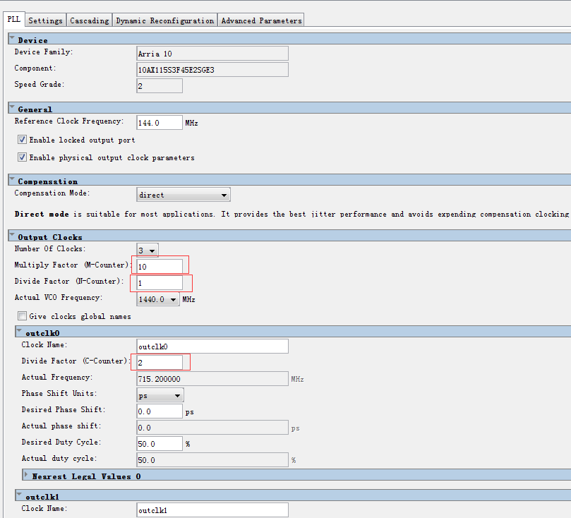
关于TX IOPLL(用于配置HDMI)的参数设置
void GPLL_RECONFIG(int GPLL_RANGE, int COLOR_DEPTH)
{
IOWR(WD_TIMER_BASE, 0x0, 0x0); // clear timeout flag
IOWR(WD_TIMER_BASE, 0x2, 0x1); // reset internal counter
IOWR(WD_TIMER_BASE, 0x1, 0x4); // start timer
switch (GPLL_RANGE)
{
case 0: // <50MHz
GPLL_RCFG_WRITE(0x90, 0x00000F0F); // m 30
GPLL_RCFG_WRITE(0xA0, 0x00010000); // n 1
GPLL_RCFG_WRITE(0xC0, 0x00000303); // c0 6
GPLL_RCFG_WRITE(0xC1, 0x00001E1E); // c1 60
if (COLOR_DEPTH == 0) GPLL_RCFG_WRITE(0xC2, 0x00001E1E); // c2 60
else if (COLOR_DEPTH == 1) GPLL_RCFG_WRITE(0xC2, 0x00002625); // c2 75
else if (COLOR_DEPTH == 2) GPLL_RCFG_WRITE(0xC2, 0x00002D2D); // c2 90
else GPLL_RCFG_WRITE(0xC2, 0x00003C3C); // c2 120
GPLL_RCFG_WRITE(0x20, 0x00000010); // cp
GPLL_RCFG_WRITE(0x40, 0x00000100); // bw
GPLL_RCFG_WRITE(0x00, 0x00000001); // Write trigger
break;
case 1: // <70MHz
GPLL_RCFG_WRITE(0x90, 0x00000A0A); // m 20
GPLL_RCFG_WRITE(0xA0, 0x00010000); // n 1
GPLL_RCFG_WRITE(0xC0, 0x00000202); // c0 4
GPLL_RCFG_WRITE(0xC1, 0x00001414); // c1 40
if (COLOR_DEPTH == 0) GPLL_RCFG_WRITE(0xC2, 0x00001414); // c2 40
else if (COLOR_DEPTH == 1) GPLL_RCFG_WRITE(0xC2, 0x00001919); // c2 50
else if (COLOR_DEPTH == 2) GPLL_RCFG_WRITE(0xC2, 0x00001E1E); // c2 60
else GPLL_RCFG_WRITE(0xC2, 0x00002828); // c2 80
GPLL_RCFG_WRITE(0x20, 0x0000000B); // cp
GPLL_RCFG_WRITE(0x40, 0x000000C0); // bw
GPLL_RCFG_WRITE(0x00, 0x00000001); // Write trigger
break;
case 2: // <100MHz
GPLL_RCFG_WRITE(0x90, 0x00000505); // m 10
GPLL_RCFG_WRITE(0xA0, 0x00010000); // n 1
GPLL_RCFG_WRITE(0xC0, 0x00000101); // c0 2
GPLL_RCFG_WRITE(0xC1, 0x00000A0A); // c1 20
if (COLOR_DEPTH == 0) GPLL_RCFG_WRITE(0xC2, 0x00000A0A); // c2 20
else if (COLOR_DEPTH == 1) GPLL_RCFG_WRITE(0xC2, 0x00000D0C); // c2 25
else if (COLOR_DEPTH == 2) GPLL_RCFG_WRITE(0xC2, 0x00000F0F); // c2 30
else GPLL_RCFG_WRITE(0xC2, 0x00001414); // c2 40
GPLL_RCFG_WRITE(0x20, 0x00000010); // cp
GPLL_RCFG_WRITE(0x40, 0x000000C0); // bw
GPLL_RCFG_WRITE(0x00, 0x00000001); // Write trigger
break;
case 3: // <170MHz
GPLL_RCFG_WRITE(0x90, 0x00000404); // m 8
GPLL_RCFG_WRITE(0xA0, 0x00010000); // n 1
GPLL_RCFG_WRITE(0xC0, 0x00000404); // c0 8
GPLL_RCFG_WRITE(0xC1, 0x00000808); // c1 16
if (COLOR_DEPTH == 0) GPLL_RCFG_WRITE(0xC2, 0x00000808); // c2 16
else if (COLOR_DEPTH == 1) GPLL_RCFG_WRITE(0xC2, 0x00000A0A); // c2 20
else if (COLOR_DEPTH == 2) GPLL_RCFG_WRITE(0xC2, 0x00000C0C); // c2 24
else GPLL_RCFG_WRITE(0xC2, 0x00001010); // c2 32
GPLL_RCFG_WRITE(0x20, 0x00000010); // cp
GPLL_RCFG_WRITE(0x40, 0x000000C0); // bw
GPLL_RCFG_WRITE(0x00, 0x00000001); // Write trigger
break;
case 4: // <340MHz
GPLL_RCFG_WRITE(0x90, 0x00000404); // m 8
GPLL_RCFG_WRITE(0xA0, 0x00010000); // n 1
GPLL_RCFG_WRITE(0xC0, 0x00000202); // c0 4
GPLL_RCFG_WRITE(0xC1, 0x00000404); // c1 8
if (COLOR_DEPTH == 0) GPLL_RCFG_WRITE(0xC2, 0x00000404); // c2 8
else if (COLOR_DEPTH == 1) GPLL_RCFG_WRITE(0xC2, 0x00000505); // c2 10
else if (COLOR_DEPTH == 2) GPLL_RCFG_WRITE(0xC2, 0x00000606); // c2 12
else GPLL_RCFG_WRITE(0xC2, 0x00000808); // c2 16
GPLL_RCFG_WRITE(0x20, 0x00000010); // cp
GPLL_RCFG_WRITE(0x40, 0x000000C0); // bw
GPLL_RCFG_WRITE(0x00, 0x00000001); // Write trigger
break;
case 5: // <600MHz
GPLL_RCFG_WRITE(0x90, 0x00000404); // m 8
GPLL_RCFG_WRITE(0xA0, 0x00010000); // n 1
GPLL_RCFG_WRITE(0xC0, 0x00000101); // c0 2
GPLL_RCFG_WRITE(0xC1, 0x00000202); // c1 4
if (COLOR_DEPTH == 0) GPLL_RCFG_WRITE(0xC2, 0x00000202); // c2 4
else if (COLOR_DEPTH == 1) GPLL_RCFG_WRITE(0xC2, 0x00000302); // c2 5
else if (COLOR_DEPTH == 2) GPLL_RCFG_WRITE(0xC2, 0x00000303); // c2 6
else GPLL_RCFG_WRITE(0xC2, 0x00000404); // c2 8
GPLL_RCFG_WRITE(0x20, 0x00000010); // cp
GPLL_RCFG_WRITE(0x40, 0x000000C0); // bw
GPLL_RCFG_WRITE(0x00, 0x00000001); // Write trigger
break;
default: // <600MHz
GPLL_RCFG_WRITE(0x90, 0x00000404); // m 8
GPLL_RCFG_WRITE(0xA0, 0x00010000); // n 1
GPLL_RCFG_WRITE(0xC0, 0x00000101); // c0 2
GPLL_RCFG_WRITE(0xC1, 0x00000202); // c1 4
if (COLOR_DEPTH == 0) GPLL_RCFG_WRITE(0xC2, 0x00000202); // c2 4
else if (COLOR_DEPTH == 1) GPLL_RCFG_WRITE(0xC2, 0x00000302); // c2 5
else if (COLOR_DEPTH == 2) GPLL_RCFG_WRITE(0xC2, 0x00000303); // c2 6
else GPLL_RCFG_WRITE(0xC2, 0x00000404); // c2 8
GPLL_RCFG_WRITE(0x20, 0x00000010); // cp
GPLL_RCFG_WRITE(0x40, 0x000000C0); // bw
GPLL_RCFG_WRITE(0x00, 0x00000001); // Write trigger
break;
}
READ_GPLL_RCFG_READY ();
IOWR(WD_TIMER_BASE, 0x1, 0x8); // stop the timer
IOWR(WD_TIMER_BASE, 0x0, 0x0); // clear timeout flag
IOWR(WD_TIMER_BASE, 0x2, 0x1); // reset internal counter
}
在上面的程序中,关于COLOR_DEPTH,根据HDMI IP里面gcp的定义00:8位,01:10位,10:12位,11:16位,Nios程序中给出COLOR_DEPTH参数0,说明输出时是按8位定义的。