本文由zhangbaochong原创,转载请注明出处http://www.cnblogs.com/zhangbaochong/p/5573970.html
前面实现简单地形的教程,我们只是绘制了一个网格,这一次我们来学习一下几种基本几何体的绘制,包括平面网格、立方体、圆柱和球体等。
原来在GeometryGenerator类中只给出了CreateGrid一个方法来绘制网格,现在让我们添加其他方法绘制一些几何体。
为了方便绘制几何体方法的调用,GeometryGenerator类我们使用了单例模式。很简单,将构造函数设为private,添加一个GetInstance函数如下:
//单例模式
    static GeometryGenerator* GetInstance()
    {
        static GeometryGenerator instance;
        return &instance;
    }
这只是实现单例模式的一种方法,还有几种实现单例模式的方法就不一一说明了。
1.基本几何体绘制方法
下面介绍几种常见几何体的绘制方法(代码均参考dx11龙书)。
1.1网格
网格可以说是最常见同时也是最重要的,像实现地形水面等都离不开网格。生成一个网格首先要给出网格的宽和高,以及在宽和高上划分的格子数。
看龙书中给出的一张图片就明白了:
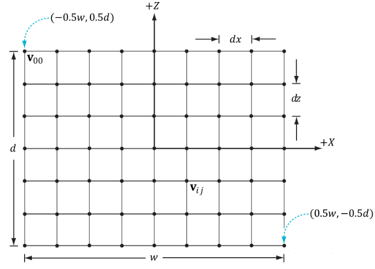
由此,顶点的坐标就很容易生成了。
顶点索引的计算关键是推导出一个用于求构成第i行,第j列的顶点处右下方两个三角形的顶点索引的通用公式。
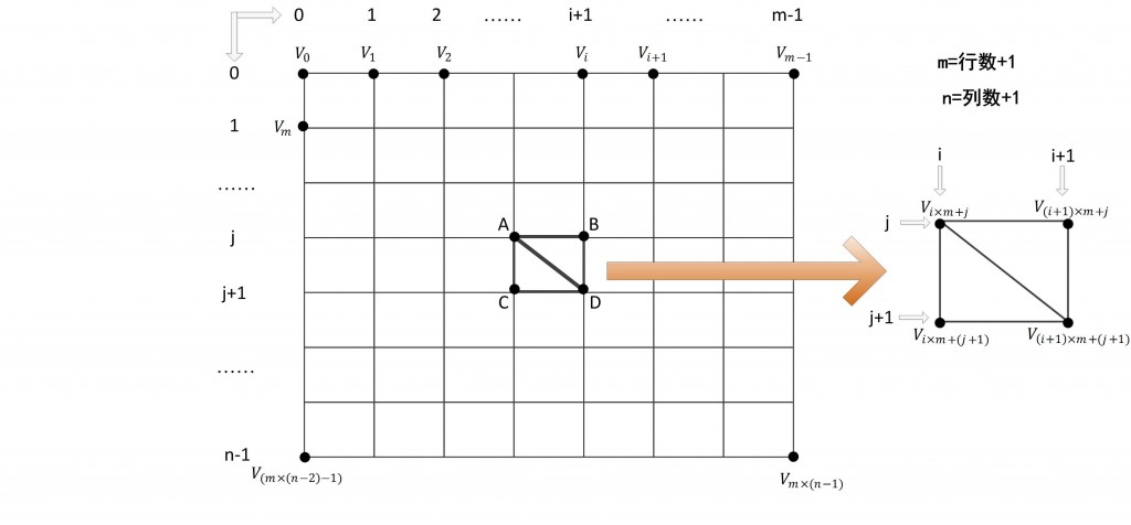
对顶点缓存中的任意一点A,如果该点位于地形中的第i行、第j列的话,那么该点在顶点缓存中所对应的位置应该就是i*m+j(m为每行的顶点数)。如果A点在索引缓存中的位置为k的话,那么A点为起始点构成的三角形ABC中,B、C顶点在顶点缓存中的位置就为(i+1)x m+j和i x m+(j+1)。且B点索引值为k+1,C点索引值为k+2.这样。这样,公式就可以推导为如下:
三角形ABC=【i*每行顶点数+j,i*每行顶点数+(j+1),(i+1)*行顶点数+j】
三角形CBD=【(i+1)*每行顶点数+j,i*每行顶点数+(j+1),(i+1)*行顶点数+(j+1)】
 1 void GeometryGenerator::CreateGrid(float width, float height, UINT m, UINT n, MeshData &mesh)
 2 {
 3     mesh.vertices.clear();
 4     mesh.indices.clear();
 5     //每行顶点数、每列顶点数
 6     UINT nVertsRow = m + 1;
 7     UINT nVertsCol = n + 1;
 8     //起始x、z坐标
 9     float oX = -width * 0.5f;
10     float oZ = height * 0.5f;
11     //每一格坐标变化
12     float dx = width / m;
13     float dz = height / n;
14
15     //顶点总数量:nVertsRow * nVertsCol
16     mesh.vertices.resize(nVertsRow * nVertsCol);
17
18     //逐个添加顶点
19     for (UINT i = 0; i < nVertsCol; ++i)
20     {
21         float tmpZ = oZ - dz * i;
22         for (UINT j = 0; j < nVertsRow; ++j)
23         {
24             UINT index = nVertsRow * i + j;
25             mesh.vertices[index].pos.x = oX + dx * j;
26             mesh.vertices[index].pos.y = 0.f;
27             mesh.vertices[index].pos.z = tmpZ;
28
29             mesh.vertices[index].normal = XMFLOAT3(0.f, 1.f, 0.f);
30             mesh.vertices[index].tangent = XMFLOAT3(1.f, 0.f, 0.f);
31
32             mesh.vertices[index].tex = XMFLOAT2(dx*i, dx*j);
33         }
34     }
35
36     //总格子数量:m * n
37     //因此总索引数量: 6 * m * n
38     UINT nIndices = m * n * 6;
39     mesh.indices.resize(nIndices);
40     UINT tmp = 0;
41     for (UINT i = 0; i < n; ++i)
42     {
43         for (UINT j = 0; j < m; ++j)
44         {
45             mesh.indices[tmp] = i * nVertsRow + j;
46             mesh.indices[tmp + 1] = i * nVertsRow + j + 1;
47             mesh.indices[tmp + 2] = (i + 1) * nVertsRow + j;
48             mesh.indices[tmp + 3] = i * nVertsRow + j + 1;
49             mesh.indices[tmp + 4] = (i + 1) * nVertsRow + j + 1;
50             mesh.indices[tmp + 5] = (i + 1) * nVertsRow + j;
51
52             tmp += 6;
53         }
54     }
55 }
1.2立方体
立方体的绘制就很简单了,一个立方体只需要提供三维方向上的长度。有一点与之前绘制彩色立方体时不一样的是,我们这里创建立方体用到24个顶点(每个面4个),而之前彩色立方体只用到了8个顶点(每个顶点被3个面共享)。这是因为在后面学习过程中我们需要顶点的法线坐标,而一个顶点相对于其连接的3个面来说,法线完全不同,因此无法共享顶点。


  1 void GeometryGenerator::CreateBox(float width, float height, float depth, MeshData &mesh)
  2 {
  3     mesh.vertices.clear();
  4     mesh.indices.clear();
  5
  6     //一共24个顶点(每面4个)
  7     mesh.vertices.resize(24);
  8     //一共36个索引(每面6个)
  9     mesh.indices.resize(36);
 10
 11     float halfW = width * 0.5f;
 12     float halfH = height * 0.5f;
 13     float halfD = depth * 0.5f;
 14
 15     //眼睛面向z轴正方向
 16     //构建顶点
 17     //前面
 18     mesh.vertices[0].pos = XMFLOAT3(-halfW, -halfH, -halfD);
 19     mesh.vertices[0].normal = XMFLOAT3(0.f, 0.f, -1.f);
 20     mesh.vertices[0].tangent = XMFLOAT3(1.f, 0.f, 0.f);
 21     mesh.vertices[0].tex = XMFLOAT2(0.f, 1.f);
 22     mesh.vertices[1].pos = XMFLOAT3(-halfW, halfH, -halfD);
 23     mesh.vertices[1].normal = XMFLOAT3(0.f, 0.f, -1.f);
 24     mesh.vertices[1].tangent = XMFLOAT3(1.f, 0.f, 0.f);
 25     mesh.vertices[1].tex = XMFLOAT2(0.f, 0.f);
 26     mesh.vertices[2].pos = XMFLOAT3(halfW, halfH, -halfD);
 27     mesh.vertices[2].normal = XMFLOAT3(0.f, 0.f, -1.f);
 28     mesh.vertices[2].tangent = XMFLOAT3(1.f, 0.f, 0.f);
 29     mesh.vertices[2].tex = XMFLOAT2(1.f, 0.f);
 30     mesh.vertices[3].pos = XMFLOAT3(halfW, -halfH, -halfD);
 31     mesh.vertices[3].normal = XMFLOAT3(0.f, 0.f, -1.f);
 32     mesh.vertices[3].tangent = XMFLOAT3(1.f, 0.f, 0.f);
 33     mesh.vertices[3].tex = XMFLOAT2(1.f, 1.f);
 34     //左侧面
 35     mesh.vertices[4].pos = XMFLOAT3(-halfW, -halfH, halfD);
 36     mesh.vertices[4].normal = XMFLOAT3(-1.f, 0.f, 0.f);
 37     mesh.vertices[4].tangent = XMFLOAT3(0.f, 0.f, -1.f);
 38     mesh.vertices[4].tex = XMFLOAT2(0.f, 1.f);
 39     mesh.vertices[5].pos = XMFLOAT3(-halfW, halfH, halfD);
 40     mesh.vertices[5].normal = XMFLOAT3(-1.f, 0.f, 0.f);
 41     mesh.vertices[5].tangent = XMFLOAT3(0.f, 0.f, -1.f);
 42     mesh.vertices[5].tex = XMFLOAT2(0.f, 0.f);
 43     mesh.vertices[6].pos = XMFLOAT3(-halfW, halfH, -halfD);
 44     mesh.vertices[6].normal = XMFLOAT3(-1.f, 0.f, 0.f);
 45     mesh.vertices[6].tangent = XMFLOAT3(0.f, 0.f, -1.f);
 46     mesh.vertices[6].tex = XMFLOAT2(1.f, 0.f);
 47     mesh.vertices[7].pos = XMFLOAT3(-halfW, -halfH, -halfD);
 48     mesh.vertices[7].normal = XMFLOAT3(-1.f, 0.f, 0.f);
 49     mesh.vertices[7].tangent = XMFLOAT3(0.f, 0.f, -1.f);
 50     mesh.vertices[7].tex = XMFLOAT2(1.f, 1.f);
 51     //背面
 52     mesh.vertices[8].pos = XMFLOAT3(halfW, -halfH, halfD);
 53     mesh.vertices[8].normal = XMFLOAT3(0.f, 0.f, 1.f);
 54     mesh.vertices[8].tangent = XMFLOAT3(-1.f, 0.f, 0.f);
 55     mesh.vertices[8].tex = XMFLOAT2(0.f, 1.f);
 56     mesh.vertices[9].pos = XMFLOAT3(halfW, halfH, halfD);
 57     mesh.vertices[9].normal = XMFLOAT3(0.f, 0.f, 1.f);
 58     mesh.vertices[9].tangent = XMFLOAT3(-1.f, 0.f, 0.f);
 59     mesh.vertices[9].tex = XMFLOAT2(0.f, 0.f);
 60     mesh.vertices[10].pos = XMFLOAT3(-halfW, halfH, halfD);
 61     mesh.vertices[10].normal = XMFLOAT3(0.f, 0.f, 1.f);
 62     mesh.vertices[10].tangent = XMFLOAT3(-1.f, 0.f, 0.f);
 63     mesh.vertices[10].tex = XMFLOAT2(1.f, 0.f);
 64     mesh.vertices[11].pos = XMFLOAT3(-halfW, -halfH, halfD);
 65     mesh.vertices[11].normal = XMFLOAT3(0.f, 0.f, 1.f);
 66     mesh.vertices[11].tangent = XMFLOAT3(-1.f, 0.f, 0.f);
 67     mesh.vertices[11].tex = XMFLOAT2(1.f, 1.f);
 68     //右侧面
 69     mesh.vertices[12].pos = XMFLOAT3(halfW, -halfH, -halfD);
 70     mesh.vertices[12].normal = XMFLOAT3(1.f, 0.f, 0.f);
 71     mesh.vertices[12].tangent = XMFLOAT3(0.f, 0.f, 1.f);
 72     mesh.vertices[12].tex = XMFLOAT2(0.f, 1.f);
 73     mesh.vertices[13].pos = XMFLOAT3(halfW, halfH, -halfD);
 74     mesh.vertices[13].normal = XMFLOAT3(1.f, 0.f, 0.f);
 75     mesh.vertices[13].tangent = XMFLOAT3(0.f, 0.f, 1.f);
 76     mesh.vertices[13].tex = XMFLOAT2(0.f, 0.f);
 77     mesh.vertices[14].pos = XMFLOAT3(halfW, halfH, halfD);
 78     mesh.vertices[14].normal = XMFLOAT3(1.f, 0.f, 0.f);
 79     mesh.vertices[14].tangent = XMFLOAT3(0.f, 0.f, 1.f);
 80     mesh.vertices[14].tex = XMFLOAT2(1.f, 0.f);
 81     mesh.vertices[15].pos = XMFLOAT3(halfW, -halfH, halfD);
 82     mesh.vertices[15].normal = XMFLOAT3(1.f, 0.f, 0.f);
 83     mesh.vertices[15].tangent = XMFLOAT3(0.f, 0.f, 1.f);
 84     mesh.vertices[15].tex = XMFLOAT2(1.f, 1.f);
 85     //上面
 86     mesh.vertices[16].pos = XMFLOAT3(-halfW, halfH, -halfD);
 87     mesh.vertices[16].normal = XMFLOAT3(0.f, 1.f, 0.f);
 88     mesh.vertices[16].tangent = XMFLOAT3(1.f, 0.f, 0.f);
 89     mesh.vertices[16].tex = XMFLOAT2(0.f, 1.f);
 90     mesh.vertices[17].pos = XMFLOAT3(-halfW, halfH, halfD);
 91     mesh.vertices[17].normal = XMFLOAT3(0.f, 1.f, 0.f);
 92     mesh.vertices[17].tangent = XMFLOAT3(1.f, 0.f, 0.f);
 93     mesh.vertices[17].tex = XMFLOAT2(0.f, 0.f);
 94     mesh.vertices[18].pos = XMFLOAT3(halfW, halfH, halfD);
 95     mesh.vertices[18].normal = XMFLOAT3(0.f, 1.f, 0.f);
 96     mesh.vertices[18].tangent = XMFLOAT3(1.f, 0.f, 0.f);
 97     mesh.vertices[18].tex = XMFLOAT2(1.f, 0.f);
 98     mesh.vertices[19].pos = XMFLOAT3(halfW, halfH, -halfD);
 99     mesh.vertices[19].normal = XMFLOAT3(0.f, 1.f, 0.f);
100     mesh.vertices[19].tangent = XMFLOAT3(1.f, 0.f, 0.f);
101     mesh.vertices[19].tex = XMFLOAT2(1.f, 1.f);
102     //底面
103     mesh.vertices[20].pos = XMFLOAT3(-halfW, -halfH, halfD);
104     mesh.vertices[20].normal = XMFLOAT3(0.f, -1.f, 0.f);
105     mesh.vertices[20].tangent = XMFLOAT3(1.f, 0.f, 0.f);
106     mesh.vertices[20].tex = XMFLOAT2(0.f, 1.f);
107     mesh.vertices[21].pos = XMFLOAT3(-halfW, -halfH, -halfD);
108     mesh.vertices[21].normal = XMFLOAT3(0.f, -1.f, 0.f);
109     mesh.vertices[21].tangent = XMFLOAT3(1.f, 0.f, 0.f);
110     mesh.vertices[21].tex = XMFLOAT2(0.f, 0.f);
111     mesh.vertices[22].pos = XMFLOAT3(halfW, -halfH, -halfD);
112     mesh.vertices[22].normal = XMFLOAT3(0.f, -1.f, 0.f);
113     mesh.vertices[22].tangent = XMFLOAT3(1.f, 0.f, 0.f);
114     mesh.vertices[22].tex = XMFLOAT2(1.f, 0.f);
115     mesh.vertices[23].pos = XMFLOAT3(halfW, -halfH, halfD);
116     mesh.vertices[23].normal = XMFLOAT3(0.f, -1.f, 0.f);
117     mesh.vertices[23].tangent = XMFLOAT3(1.f, 0.f, 0.f);
118     mesh.vertices[23].tex = XMFLOAT2(1.f, 1.f);
119
120     //构建索引
121     mesh.indices[0] = 0;
122     mesh.indices[1] = 1;
123     mesh.indices[2] = 2;
124     mesh.indices[3] = 0;
125     mesh.indices[4] = 2;
126     mesh.indices[5] = 3;
127
128     mesh.indices[6] = 4;
129     mesh.indices[7] = 5;
130     mesh.indices[8] = 6;
131     mesh.indices[9] = 4;
132     mesh.indices[10] = 6;
133     mesh.indices[11] = 7;
134
135     mesh.indices[12] = 8;
136     mesh.indices[13] = 9;
137     mesh.indices[14] = 10;
138     mesh.indices[15] = 8;
139     mesh.indices[16] = 10;
140     mesh.indices[17] = 11;
141
142     mesh.indices[18] = 12;
143     mesh.indices[19] = 13;
144     mesh.indices[20] = 14;
145     mesh.indices[21] = 12;
146     mesh.indices[22] = 14;
147     mesh.indices[23] = 15;
148
149     mesh.indices[24] = 16;
150     mesh.indices[25] = 17;
151     mesh.indices[26] = 18;
152     mesh.indices[27] = 16;
153     mesh.indices[28] = 18;
154     mesh.indices[29] = 19;
155
156     mesh.indices[30] = 20;
157     mesh.indices[31] = 21;
158     mesh.indices[32] = 22;
159     mesh.indices[33] = 20;
160     mesh.indices[34] = 22;
161     mesh.indices[35] = 23;
162 }
1.3圆柱
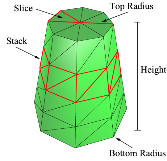
为了构建一个圆柱,需要提供如下信息:圆柱的上口半径(topRadius),下口半径(bottomRadius),高度(height)。此外,为了指定圆柱的精细度,还需要指定两个参数,一个为没高度方向上平均划分的个数(stack),另一个为沿圆周方向等分的个数(slice)。
可以根据龙书中给出的图理解一下:
 1 void GeometryGenerator::CreateCylinder(float topRadius, float bottomRadius, float height, int slice, int stack, MeshData &mesh)
 2 {
 3     mesh.vertices.clear();
 4     mesh.indices.clear();
 5
 6     //从上到下每个stack半径变化量:dRadius
 7     float dRadius = (bottomRadius - topRadius) / stack;
 8     //每个stack高度:dHeight
 9     float dHeight = height / stack;
10
11     //每个圆周上顶点数量:slice+1
12     int vertsPerRow = slice + 1;
13     //顶点行数:stack+1
14     int nRows = stack + 1;
15
16     //总顶点数
17     int nVerts = vertsPerRow * nRows;
18     //总索引数
19     int nIndices = slice * stack * 6;
20
21     mesh.vertices.resize(nVerts);
22     mesh.indices.resize(nIndices);
23
24     //顶部Y坐标
25     float topY = height * 0.5f;
26
27     for (int i = 0; i < nRows; ++i)
28     {
29         float tmpY = topY - dHeight * i;
30         float tmpRadius = topRadius + i * dRadius;
31
32         for (int j = 0; j < vertsPerRow; ++j)
33         {
34             float theta = XM_2PI * j / slice;
35             int index = i * vertsPerRow + j;
36             mesh.vertices[index].pos = XMFLOAT3(tmpRadius*cos(theta), tmpY, tmpRadius*sin(theta));
37         }
38     }
39
40     UINT tmp(0);
41     for (int i = 0; i < stack; ++i)
42     {
43         for (int j = 0; j < slice; ++j)
44         {
45             mesh.indices[tmp] = i * vertsPerRow + j;
46             mesh.indices[tmp + 1] = (i + 1) * vertsPerRow + j + 1;
47             mesh.indices[tmp + 2] = (i + 1) * vertsPerRow + j;
48             mesh.indices[tmp + 3] = i * vertsPerRow + j;
49             mesh.indices[tmp + 4] = i * vertsPerRow + j + 1;
50             mesh.indices[tmp + 5] = (i + 1) * vertsPerRow + j + 1;
51
52             tmp += 6;
53         }
54     }
55 }
1.4球
绘制球基本参数只有一个半径,但是同圆柱一样为了指定精细程度也要给出stack和slice两个参数,这里slice是从上极点沿球面到下极点的180度角等分。具体绘制可以看代码理解:
 1 void GeometryGenerator::CreateSphere(float radius, int slice, int stack, MeshData &mesh)
 2 {
 3
 4     mesh.vertices.clear();
 5     mesh.indices.clear();
 6
 7     int vertsPerRow = slice + 1;
 8     int nRows = stack - 1;
 9
10     int nVerts = vertsPerRow * nRows + 2;
11     int nIndices = (nRows - 1)*slice * 6 + slice * 6;
12
13     mesh.vertices.resize(nVerts);
14     mesh.indices.resize(nIndices);
15
16     for (int i = 1; i <= nRows; ++i)
17     {
18         float phy = XM_PI * i / stack;
19         float tmpRadius = radius * sin(phy);
20         for (int j = 0; j < vertsPerRow; ++j)
21         {
22             float theta = XM_2PI * j / slice;
23             UINT index = (i - 1)*vertsPerRow + j;
24
25             float x = tmpRadius*cos(theta);
26             float y = radius*cos(phy);
27             float z = tmpRadius*sin(theta);
28
29             //位置坐标
30             mesh.vertices[index].pos = XMFLOAT3(x, y, z);
31             //法线
32             XMVECTOR N = XMVectorSet(x, y, z, 0.f);
33             XMStoreFloat3(&mesh.vertices[index].normal, XMVector3Normalize(N));
34             //切线
35             XMVECTOR T = XMVectorSet(-sin(theta), 0.f, cos(theta), 0.f);
36             XMStoreFloat3(&mesh.vertices[index].tangent, XMVector3Normalize(T));
37             //纹理坐标
38             mesh.vertices[index].tex = XMFLOAT2(j*1.f / slice, i*1.f / stack);
39         }
40     }
41
42     int size = vertsPerRow * nRows;
43     //添加顶部和底部两个顶点信息
44     mesh.vertices[size].pos = XMFLOAT3(0.f, radius, 0.f);
45     mesh.vertices[size].normal = XMFLOAT3(0.f, 1.f, 0.f);
46     mesh.vertices[size].tangent = XMFLOAT3(1.f, 0.f, 0.f);
47     mesh.vertices[size].tex = XMFLOAT2(0.f, 0.f);
48
49     mesh.vertices[size + 1].pos = XMFLOAT3(0.f, -radius, 0.f);
50     mesh.vertices[size + 1].normal = XMFLOAT3(0.f, -1.f, 0.f);
51     mesh.vertices[size + 1].tangent = XMFLOAT3(1.f, 0.f, 0.f);
52     mesh.vertices[size + 1].tex = XMFLOAT2(0.f, 1.f);
53
54     UINT tmp(0);
55     int start1 = 0;
56     int start2 = mesh.vertices.size() - vertsPerRow - 2;
57     int top = size;
58     int bottom = size + 1;
59     for (int i = 0; i < slice; ++i)
60     {
61         mesh.indices[tmp] = top;
62         mesh.indices[tmp + 1] = start1 + i + 1;
63         mesh.indices[tmp + 2] = start1 + i;
64
65         tmp += 3;
66     }
67
68     for (int i = 0; i < slice; ++i)
69     {
70         mesh.indices[tmp] = bottom;
71         mesh.indices[tmp + 1] = start2 + i;
72         mesh.indices[tmp + 2] = start2 + i + 1;
73
74         tmp += 3;
75     }
76
77     for (int i = 0; i < nRows - 1; ++i)
78     {
79         for (int j = 0; j < slice; ++j)
80         {
81             mesh.indices[tmp] = i * vertsPerRow + j;
82             mesh.indices[tmp + 1] = (i + 1) * vertsPerRow + j + 1;
83             mesh.indices[tmp + 2] = (i + 1) * vertsPerRow + j;
84             mesh.indices[tmp + 3] = i * vertsPerRow + j;
85             mesh.indices[tmp + 4] = i * vertsPerRow + j + 1;
86             mesh.indices[tmp + 5] = (i + 1) * vertsPerRow + j + 1;
87
88             tmp += 6;
89         }
90     }
91 }
2.场景绘制
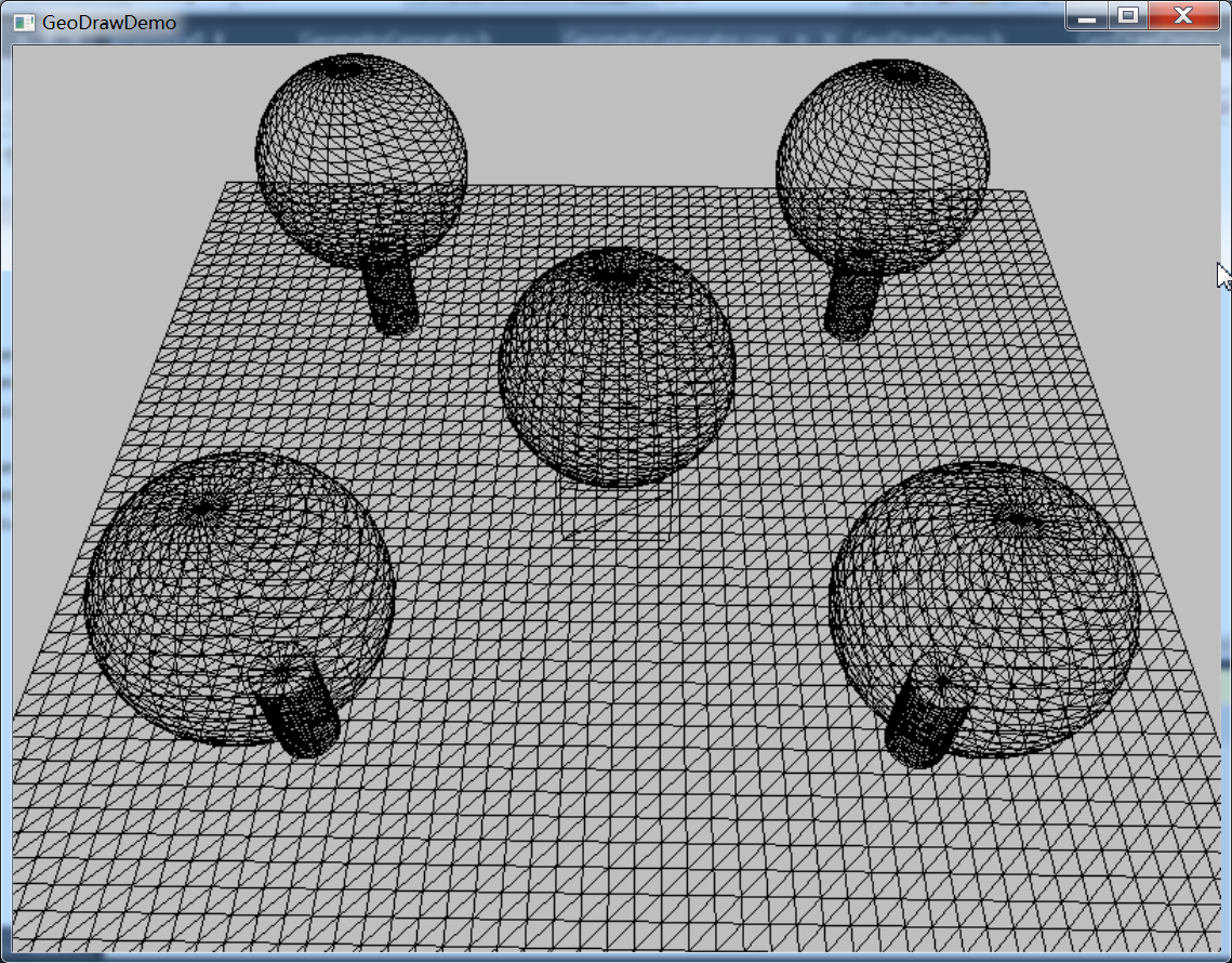
2.1最终效果
2.2多个几何体共享顶点索引缓冲区
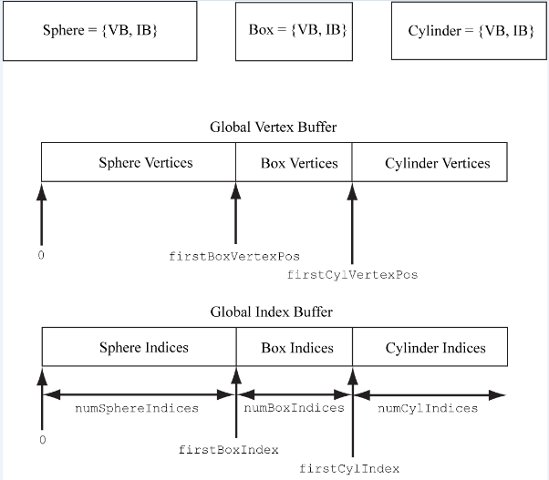
我们一共绘制了四种几何体:网格、立方体、球和圆柱,它们公用了一个顶点和索引缓冲区。这样我们就需要在其中找出每个几何体对应的位置。
为了在顶点、索引缓冲区中找到一个物体对应的位置,我们使用三个参数:该物体在顶点缓冲区中的起始位置(VStart),索引缓冲区中的起始位置(IStart),以及索引总数(totalIndices)。看龙书中的一幅图就很容易理解了:
2.3设为线框模式绘制
在Render函数中创建一个栅格化状态ID3D11RasterizerState ,状态描述中FillMode设为D3D11_FILL_WIREFRAME即可
 1 //设置为线框绘制模式
 2     D3D11_RASTERIZER_DESC rsDesc;
 3     ZeroMemory(&rsDesc, sizeof(rsDesc));
 4     rsDesc.CullMode = D3D11_CULL_BACK;
 5     rsDesc.DepthClipEnable = true;
 6     //D3D11_FILL_WIREFRAME以线框模式绘制,D3D11_FILL_SOLID是以实体模式绘制
 7     rsDesc.FillMode = D3D11_FILL_WIREFRAME;
 8     rsDesc.FrontCounterClockwise = false;
 9     ID3D11RasterizerState *rsState(nullptr);
10     m_pd3dDevice->CreateRasterizerState(&rsDesc, &rsState);
11     m_pImmediateContext->RSSetState(rsState);
源码下载:http://files.cnblogs.com/files/zhangbaochong/GeoDrawDemo.zip