1. 4阶m序列生成器
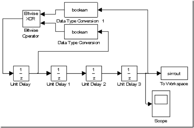
Simulink模型如下:
其中,可以在Unit Delay属性中设置初始值为1000,由于Unit Delay输出为double,所以要将其转为Boolean以便进行模二加运算,使用XOR实现。
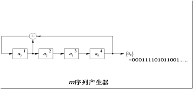
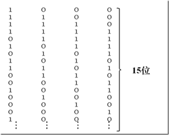
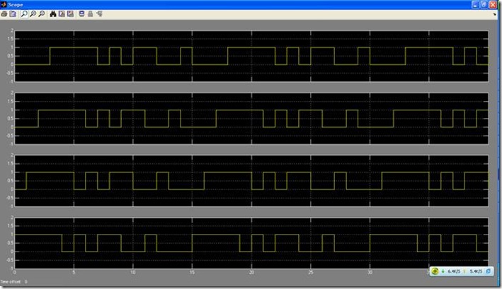
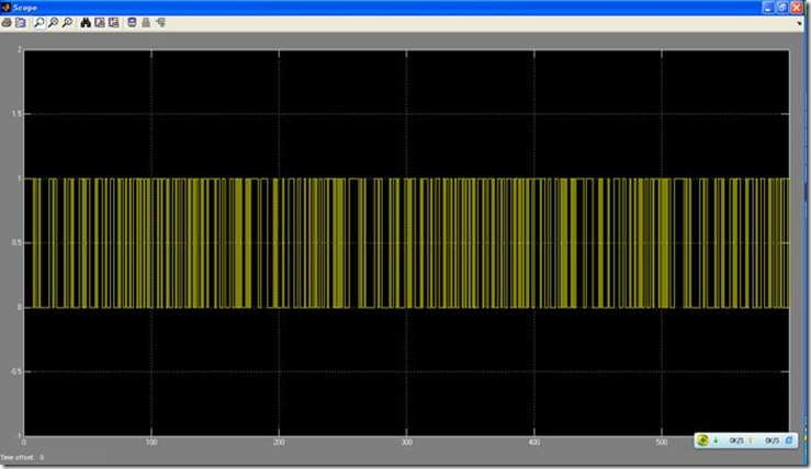
下面分别是最后一级和所有级的输出波形,可以看出,与上面的是一致的。
Verilog实现
`timescale 1ns / 1ps
//////////////////////////////////////////////////////////////////////////////////
// Company:
// Engineer:
//
// Create Date: 11:02:17 05/01/2012
// Design Name:
// Module Name: PNcode
// Project Name:
//////////////////////////////////////////////////////////////////////////////////
module PNcode(
clk,
rst,
PNstate,
PNout
);
input clk;
input rst;
output PNstate;
output PNout;
// PN code n = 4, f(x) = 1 + x + x^4
parameter order = 4;
reg PNout = 0;
reg [order-1 : 0] PNstate = 0;
always @ (posedge clk)
if(rst == 1)
begin
PNout <= 0;
PNstate <= 4'b1000; // PN seed = b1000
end
else
begin
PNout <= PNstate[0];
PNstate <= {PNstate[3]+PNstate[0], PNstate[3:1]};
end
endmodule
测试文件:
`timescale 1ns / 1ps
////////////////////////////////////////////////////////////////////////////////
// Company:
// Engineer:
//
// Create Date: 14:37:43 05/01/2012
// Design Name: PNcode
// Module Name: E:/me/CAST/Project/FPGAcomm/PNcode/PNcode_tb.v
// Project Name: PNcode
//
////////////////////////////////////////////////////////////////////////////////
module PNcode_tb;
// Inputs
reg clk;
reg rst;
// Outputs
wire [3:0] PNstate;
wire PNout;
// Instantiate the Unit Under Test (UUT)
PNcode uut (
.clk(clk),
.rst(rst),
.PNstate(PNstate),
.PNout(PNout)
);
initial begin
// Initialize Inputs
clk = 0;
rst = 1;
// Wait 100 ns for global reset to finish
#100;
rst = 0;
// Add stimulus here
end
always begin
forever #10 clk = !clk;
end
endmodule
clk使用一个单独的always模块
输出序列:0 0 0 1 1 1 1 0 1 0 1 1 0 0 1 0 0 0 1
2. 8阶m序列生成器,初始全为1
