参考文章: https://www.imgtec.com/blog/implementing-fast-ray-traced-soft-shadows-in-a-game-engine/
完成的工程: https://github.com/yangrc1234/ScreenSpaceShadow

(一个例子,注意靠近立柱的部分的阴影较为锐利,远离的部分更加模糊)
Penumbra
现实生活中,距离遮挡物越近的地方,其阴影会更加锐利;反之则更加模糊。这一片介于被照亮和阴影中间的区域被称为Penumbra。我们用如下公式去计算Penumbra的大小:
对于太阳光,我们可以认为Light Size / Total Distance是一个常数。当这个常数大时,模糊效果就会更大。
在实现过程中,我们生成两张贴图,一张是阴影贴图,保存某个点上是否有阴影;另一个保存一个点到其遮挡物的距离。我们可以在一张贴图里的不同通道保存这两个信息。
生成贴图完毕后,我们在第二个pass里对阴影贴图做模糊。其中模糊的半径根据该点上的遮挡物距离决定。如果一个点不在阴影中,则去搜索最靠近的阴影中的点(如果没搜到,说明该点被完全照亮),然后用这个点的遮挡物距离进行模糊。搜索时我们直接在该点的水平方向或者垂直方向上的点进行搜索。
之后将模糊得到的结果和原有的屏幕阴影做Blend即可。
具体实现
我们使用2个CommandBuffer去实现这个效果。脚本都附在Directional Light下。
第一个CommandBuffer在LightEvent.BeforeScreenspaceMask执行。在这一步我们渲染上面提到的阴影贴图+遮挡物距离。
第二个CommandBuffer在LightEvent.AfterScreenspaceMask执行。在这一步中,我们的渲染目标由Unity设置为了屏幕空间阴影贴图。此时我们可以同时进行模糊以及Blend的操作。
这里分为两个CommandBuffer有两个原因,
- 除了这两个事件中,默认的RenderTarget是屏幕空间阴影贴图,我们似乎没有办法在其他地方将RenderTarget设置为这个屏幕空间阴影贴图。
- 在第一个CommandBuffer渲染完阴影贴图+遮挡物距离之后,此时RenderTarget已经改变了。而我们没有办法将RenderTarget重置成屏幕空间阴影贴图。所以等到LightEvent.AfterScreenspaceMask的时候切换回RenderTarget吧。
听起来有点捉鸡,不知道是我太菜还是CommandBuffer太菜……
using System.Collections;
using System.Collections.Generic;
using UnityEngine;
using UnityEngine.Rendering;

[RequireComponent(typeof(Light))]
public class ScreenSpaceShadow : MonoBehaviour {

    public Shader sssShader;

    private Light dlight { get {
            return GetComponent<Light>();
        } }

    private Material _mat;
    private Material mat {
        get {
            return _mat ?? (_mat = new Material(sssShader));
        }
    }

    private CommandBuffer cmdBuf;   //executed before shadow map.
    private CommandBuffer afterCmdBuf;
    private RenderTexture tempScreenSpaceShadow;
    private void UpdateCommandBuffers() {
        if (tempScreenSpaceShadow != null)
            DestroyImmediate(tempScreenSpaceShadow);
        tempScreenSpaceShadow = new RenderTexture(Screen.width, Screen.height, 0,RenderTextureFormat.RGFloat);        //R channel stands for dentisy, G stands for occluder distance.
        tempScreenSpaceShadow.filterMode = FilterMode.Point;

        cmdBuf = new CommandBuffer();
        cmdBuf.Blit(null, tempScreenSpaceShadow, mat, 0);          //first pass. render a dentisy/occluder distance buffer.
        afterCmdBuf = new CommandBuffer();
        afterCmdBuf.Blit(tempScreenSpaceShadow, BuiltinRenderTextureType.CurrentActive, mat, 1);    //second pass. blur the dentisy and blend final result into current screen shadow map.
    }

    //doesn't work for multi camera.
    //I can't find a way to make it compatitable with multi camera.
    //if you know how to access correct view matrix inside shader(Currently UNITY_MATRIX_V doesn't work in Unity 2017.1, or I misunderstand the meaning of UNITY_MATRIX_V? ), you can remove this, and multi camera will work.
    private void Update() {
        mat.SetMatrix("_WorldToView", Camera.main.worldToCameraMatrix);
    }

    private void OnEnable() {
        UpdateCommandBuffers();
        dlight.AddCommandBuffer(LightEvent.BeforeScreenspaceMask, cmdBuf);
        dlight.AddCommandBuffer(LightEvent.AfterScreenspaceMask, afterCmdBuf);
    }

    private void OnDisable() {
        dlight.RemoveCommandBuffer(LightEvent.BeforeScreenspaceMask, cmdBuf);
        dlight.RemoveCommandBuffer(LightEvent.AfterScreenspaceMask, afterCmdBuf);
    }
}
接下来是Shader的实现。之前的文章中我们已经提过了屏幕空间光线追踪的原理以及实现。这里我直接贴出相关函数的代码。
#ifndef _YRC_SCREEN_SPACE_RAYTRACE_
#define _YRC_SCREEN_SPACE_RAYTRACE_

//convenient function.
bool RayIntersect(float raya, float rayb, float2 sspt,float thickness) {
	if (raya > rayb) {
		float t = raya;
		raya = rayb;
		rayb = t;
	}

#if 1		//by default we use fixed thickness.
	float screenPCameraDepth = -LinearEyeDepth(tex2Dlod(_CameraDepthTexture, float4(sspt / 2 + 0.5, 0, 0)).r);
	return raya < screenPCameraDepth && rayb > screenPCameraDepth - thickness;
#else
	float backZ = tex2Dlod(_BackfaceTex, float4(sspt / 2 + 0.5, 0, 0)).r;
	return raya < backZ && rayb > screenPCameraDepth;
#endif
}


bool traceRay(float3 start, float3 direction, float jitter, float4 texelSize,float maxRayLength, float maxStepCount, float pixelStride, float pixelThickness, out float2 hitPixel, out float marchPercent,out float hitZ,out float rayLength) {
	//clamp raylength to near clip plane.
	rayLength = ((start.z + direction.z * maxRayLength) > -_ProjectionParams.y) ?
		(-_ProjectionParams.y - start.z) / direction.z : maxRayLength;

	float3 end = start + direction * rayLength;

	float4 H0 = mul(unity_CameraProjection, float4(start, 1));
	float4 H1 = mul(unity_CameraProjection, float4(end, 1));

	float2 screenP0 = H0.xy / H0.w;
	float2 screenP1 = H1.xy / H1.w;

	float k0 = 1.0 / H0.w;
	float k1 = 1.0 / H1.w;

	float Q0 = start.z * k0;
	float Q1 = end.z * k1;

	if (abs(dot(screenP1 - screenP0, screenP1 - screenP0)) < 0.00001) {
		screenP1 += texelSize.xy;
	}
	float2 deltaPixels = (screenP1 - screenP0) * texelSize.zw;
	float step;	//the sample rate.
	step = min(1 / abs(deltaPixels.y), 1 / abs(deltaPixels.x)); //make at least one pixel is sampled every time.

	//make sample faster.
	step *= pixelStride;
	float sampleScaler = 1.0 - min(1.0, -start.z / 100); //sample is slower when far from the screen.
	step *= 1.0 + sampleScaler;

	float interpolationCounter = step;	//by default we use step instead of 0. this avoids some glitch.

	float4 pqk = float4(screenP0, Q0, k0);
	float4 dpqk = float4(screenP1 - screenP0, Q1 - Q0, k1 - k0) * step;

	pqk += jitter * dpqk;

	float prevZMaxEstimate = start.z;

	bool intersected = false;
	UNITY_LOOP		//the logic here is a little different from PostProcessing or (casual-effect). but it's all about raymarching.
	for (int i = 1;
			i <= maxStepCount && interpolationCounter <= 1 && !intersected;
			i++,interpolationCounter += step
			) {
		pqk += dpqk;
		float rayZMin = prevZMaxEstimate;
		float rayZMax = ( pqk.z) / ( pqk.w);

		if (RayIntersect(rayZMin, rayZMax, pqk.xy - dpqk.xy / 2, pixelThickness)) {
			hitPixel = (pqk.xy - dpqk.xy / 2) / 2 + 0.5;
			marchPercent = (float)i / maxStepCount;
			intersected = true;
		}
		else {
			prevZMaxEstimate = rayZMax;
		}
	}

#if 1	  //binary search
	if (intersected) {
		pqk -= dpqk;	//one step back
		UNITY_LOOP
		for (float gapSize = pixelStride; gapSize > 1.0; gapSize /= 2) {
			dpqk /= 2;
			float rayZMin = prevZMaxEstimate;
			float rayZMax = (pqk.z) / ( pqk.w);
			if (RayIntersect(rayZMin, rayZMax, pqk.xy - dpqk.xy / 2, pixelThickness)) {		//hit, stay the same.(but ray length is halfed)

			}
			else {							//miss the hit. we should step forward
				pqk += dpqk;
				prevZMaxEstimate = rayZMax;
			}
		}
		hitPixel = (pqk.xy - dpqk.xy / 2) / 2 + 0.5;
	}
#endif
	hitZ = pqk.z / pqk.w;
	rayLength *= (hitZ - start.z) / (end.z - start.z);
	return intersected;
}


#endif
在两个pass中,我们的vertex program是相同的。代码如下:
struct appdata {
	float4 vertex : POSITION;
	float2 uv : TEXCOORD0;
};

struct v2f {
	float2 uv : TEXCOORD0;
	float4 vertex : SV_POSITION;
	float3 csRay : TEXCOORD1;        //unused during second pass.
};

v2f vert(appdata v) {
	v2f o;
	o.vertex = UnityObjectToClipPos(v.vertex);
	o.uv = v.uv;
	float4 cameraRay = float4(v.uv * 2.0 - 1.0, 1.0, 1.0);
	cameraRay = mul(unity_CameraInvProjection, cameraRay);
	o.csRay = cameraRay / cameraRay.w;
	return o;
}
第一个pass的fragment program如下:
#define RAY_LENGTH 40.0 //maximum ray length.
#define STEP_COUNT 256 //maximum sample count.
#define PIXEL_STRIDE 4 //sample multiplier. it's recommend 16 or 8.
#define PIXEL_THICKNESS (0.04 * PIXEL_STRIDE) //how thick is a pixel. correct value reduces noise.
float4 fragDentisyAndOccluder(v2f i) : SV_Target //we return dentisy in R, distance in G
{
float decodedDepth = Linear01Depth(tex2D(_CameraDepthTexture, i.uv).r);
float3 csRayOrigin = decodedDepth * i.csRay;
float3 wsNormal = tex2D(_CameraGBufferTexture2, i.uv).rgb * 2.0 - 1.0;
float3 csNormal = normalize(mul((float3x3)_WorldToView, wsNormal));
float3 wsLightDir = -_LightDir;
float3 csLightDir = normalize(mul((float3x3)_WorldToView, wsLightDir));
float2 hitPixel;
float marchPercent;
float3 debugCol;
float atten = 0;
float2 uv2 = i.uv * float2(1024,1024);
float c = (uv2.x + uv2.y) * 0.25;
float hitZ;
float rayBump = max(-0.010*csRayOrigin.z, 0.001);
float rayLength;
bool intersectd = traceRay(
csRayOrigin + csNormal * rayBump,
csLightDir,
0, //don't need jitter here.
float4(1 / 991.0, 1 / 529.0, 991.0, 529.0), //texel size.
RAY_LENGTH,
STEP_COUNT,
PIXEL_STRIDE,
PIXEL_THICKNESS,
hitPixel,
marchPercent,
hitZ,
rayLength
);
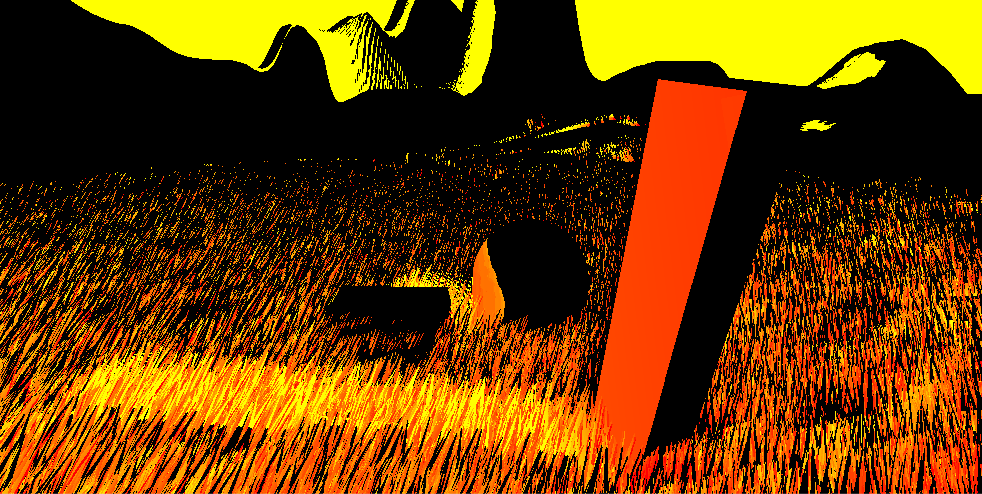
return intersectd ? float4(1 , rayLength, 0, 1) : 0;
}
当我们没有命中时,我们返回全0的结果,否则将R设置为1,同时在G通道上保存距离。
在我上面贴出的原文中,阴影贴图可以在光线追踪到透明物体时设置为0.x这样的数值,但是我们的deferred rendering肯定没有这样的操作。(原文中的硬件是专门用于光线追踪的硬件,它的光线追踪也不是屏幕空间光线追踪)所以这里的贴图应该可以压缩成一个通道,为0时表示没有阴影,非0时表示到阻挡者的距离。
生成的贴图:
第二个pass如下:
#define BLURBOX_HALFSIZE 8
#define PENUMBRA_SIZE_CONST 4
#define MAX_PENUMBRA_SIZE 8
#define DEPTH_REJECTION_EPISILON 1.0

fixed4 fragBlur(v2f i) :SV_TARGET{
	float2 dentisyAndOccluderDistance = tex2D(_MainTex,i.uv).rg;
	fixed dentisy = dentisyAndOccluderDistance.r;
	float occluderDistance = dentisyAndOccluderDistance.g;
	float maxOccluderDistance = 0;

	float3 uvOffset = float3(_MainTex_TexelSize.xy, 0);	//convenient writing here.
	for (int j = 0; j < BLURBOX_HALFSIZE; j++) {        //search on vertical and horizontal for nearest shadowed pixel.
		float top = tex2D(_MainTex, i.uv + j * uvOffset.zy).g;
		float bot = tex2D(_MainTex, i.uv - j * uvOffset.zy).g;
		float lef = tex2D(_MainTex, i.uv + j * uvOffset.xz).g;
		float rig = tex2D(_MainTex, i.uv - j * uvOffset.xz).g;
		if (top != 0 || bot != 0 || lef != 0 || rig != 0) {
			maxOccluderDistance = max(top, max(bot, max (lef, rig)));
			break;
		}
	}

	float penumbraSize = maxOccluderDistance * PENUMBRA_SIZE_CONST;

	float camDistance = LinearEyeDepth(tex2D(_CameraDepthTexture, i.uv));

	float projectedPenumbraSize = penumbraSize / camDistance;

	projectedPenumbraSize = min(1 + projectedPenumbraSize, MAX_PENUMBRA_SIZE);

	float depthtop = LinearEyeDepth(tex2D(_CameraDepthTexture, i.uv + j * uvOffset.zy));
	float depthbot = LinearEyeDepth(tex2D(_CameraDepthTexture, i.uv - j * uvOffset.zy));
	float depthlef = LinearEyeDepth(tex2D(_CameraDepthTexture, i.uv + j * uvOffset.xz));
	float depthrig = LinearEyeDepth(tex2D(_CameraDepthTexture, i.uv - j * uvOffset.xz));

	float depthdx = min(abs(depthrig - camDistance), abs(depthlef - camDistance));
	float depthdy = min(abs(depthtop - camDistance), abs(depthbot - camDistance));

	float counter = 0;
	float accumulator = 0;
	UNITY_LOOP
	for (int j = -projectedPenumbraSize; j < projectedPenumbraSize; j++) {	//xaxis
		for (int k = -projectedPenumbraSize; k < projectedPenumbraSize; k++) {	//yaxis
			float depth = LinearEyeDepth(tex2Dlod(_CameraDepthTexture, float4(i.uv + uvOffset.xy * float2(j, k),0,0)));
			if (depthdx * abs(j) + depthdy * abs(k) + DEPTH_REJECTION_EPISILON < abs(camDistance - depth))        //depth rejection
				break;
			counter += 1;
			accumulator += tex2Dlod(_MainTex, float4(i.uv + uvOffset.xy * float2(j, k),0,0)).r;
		}
	}
	return (1 - saturate(accumulator / counter));
}
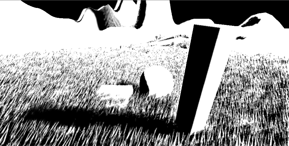
大体内容还是很好理解的。首先我们根据遮挡距离计算penumbra的大小,然后除以z值,获得屏幕空间下的penumbra的大小。然后根据这个大小去采样同样大小的屏幕空间的像素即可。
其中有一个depth rejection的操作,用于将跟当前点不是同一个平面上的采样剔除掉。具体的操作是比较采样点和当前点的深度,如果差值超过了一个阈值,则认为不在一个平面。这个阈值是通过当前点和其上下左右四个点的深度值计算得到的。具体的就不细说了。
这里返回的是光照值。此时生成的贴图是这样的:
因为我们希望原有的屏幕空间阴影和我们计算的结果结合。此时我们可以想到可以通过将两张贴图的值相乘得到最终结果。(两张贴图保存的都是光照度,阴影为0,光照为1,相乘后两张贴图的阴影融合)
我们设置Blend选项为Blend Zero SrcAlpha,此时公式为Src * Zero + Dst * SrcAlpha,即Dst * SrcAlpha,我们就得到了最终结果。
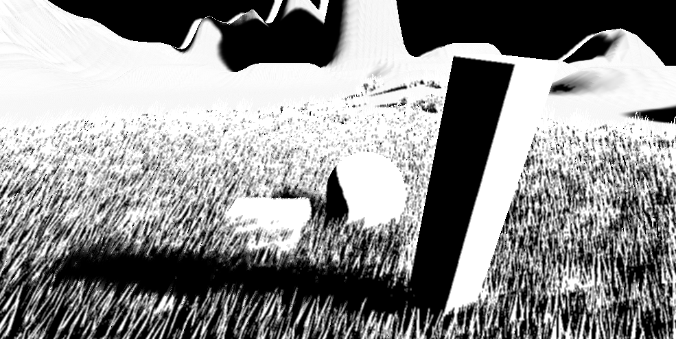 (注意后面的山的阴影,来自原本的屏幕空间阴影贴图)
总结
以上就是我的屏幕空间阴影的实现。这个实现有诸多不完善的地方,比如
-
不支持多相机。
这个问题的根本原因是UNITY_MATRIX_V在shader中不知道为什么无效了。因此我们需要在脚本中手动设置世界到相机的矩阵。在之前的屏幕空间反射中,这样的设置还没有太大的问题,但是在这里我们使用CommandBuffer注入了Directional Light的流程进行渲染,这个CommandBuffer在所有相机渲染光照的时候都会执行一次。为了保证正确,我们需要在每次渲染的时候都设置一次对应相机的矩阵。但是我现在还没有找到正确的,可以设置对应相机矩阵的方法。(OnRenderObject里使用Camera.current的矩阵进行设置并不work,不知道为什么)。 -
不支持Shadow Strength。
在Light的选项里有一个Shadow Strength。在渲染屏幕空间阴影贴图时,根据这个值,渲染出来的阴影部分强度也是不同的。但是我们渲染出来的阴影会以相乘的方式融合进去,此时整张阴影贴图的强度就变得不均匀了。也许有修改Blend选项之类的办法来解决这个问题,我暂时没想到。

(注意山上的阴影,原贴图的部分是较浅,我们的部分是黑色) -
只支持Deferred rendering。
这个效果中需要Deferred rendering的点只有屏幕光线追踪时,需要用到法线做一个起始点偏移。事实上我们是可以是可以通过深度贴图来一定程度上重建一个屏幕空间的法线信息的,但是我还没有尝试过。因此理论上我们可以将该效果改造为同时适应forward rendering与deferred rendering的一个效果。