本文版权归 XiaomaGee所有,转载请注明出处。
_____________________________________
深入交流QQ群:
A: 204255896(500人超级群,满员) B: 165201798(500人超级群,满员)
C: 215053598(200人高级群,满员) D: 215054675(200人高级群)
E: 215055211(200人高级群) F: 78538605 (500人高级群)
G:158560047(500人高级群,满员)
YY 群:7182393
YY频道:80518139(不定期语音群课)
博客:http://XiaomaGee.cnblogs.com
提示:请关注论坛和博客,以便浏览本文档最新版本
_____________________________________
一、 ARM 程序介绍
1. 写函数
1 #define fpga_write(offset, data) *((volatile unsigned short int*)(CS0_BASE + (offset << 17))) = data
其中:
- offset为空间偏移量,范围为 0~7(8个空间);
- data 为数据,16位整数,范围为 0~65535;
- CS0_BASE 为ARM连接FPGA cs0的基地址,具体内容详见原理图。
若向空间2写入1234,则调用方法为:
1 fpga_write(2,1234);
2. 读函数
1 #define fpga_read(offset) *((volatile unsigned short int*)(CS0_BASE + (offset << 17)))
其中:
- offset 为空间偏移量,范围为0~7(共8个空间);
- 范围值为16位证书,范围为0~65535;
- CS0_BASE 为ARM连接FPGAcs0的基地址,具体内容详见原理图。
若读取空间2的值,则调用方法为:
1 unsigned short int read_data;
2
3 read_data = fpga_read(2);
二、 FPGA 程序介绍
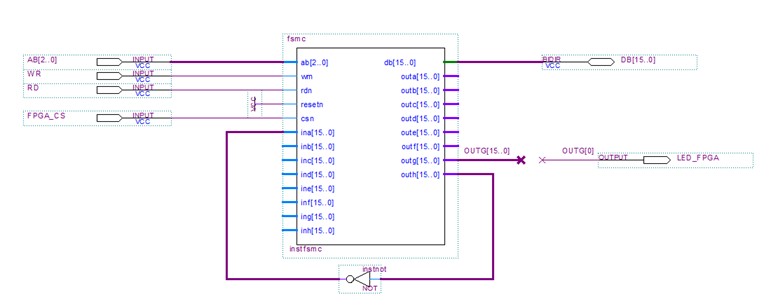
图示为FSMC 代码生成的顶层模块连接示意图,其中:
- DB[15..0] AB[18..16] WR RD CS0 连接到 ARM上;
- LED_FPGA 使用outg[0] 控制其亮和灭(可以通过面板控制);
- ina[15..0] ~ inh[15..0] 为读取数据输入,共包含8个空间,每个空间16位;
- outa[15..0]~outh[15..0]为写入空间寄存器,共8个空间,每个空间16位;
具体实现原理请参考 fsmc.v 程序。
//fsmc read / write ep4ce6 demo

module fsmc(
    ab,   //address
    db,    //data
    wrn,    //wr
    rdn,    //rd
    resetn,    //resetn
    csn,    //cs
    ina,    //input data a
    inb,    //input data b
    inc,    //input data c
    ind,    //input data d
    ine,    //input data e
    inf,    //input data f
    ing,    //input data g
    inh,    //input data h
    outa,    //output data a
    outb,    //output data a
    outc,    //output data a
    outd,    //output data a
    oute,    //output data a
    outf,    //output data a
    outg,    //output data a
    outh    //output data a
    );

    input[2:0]    ab;
    inout[15:0] db;
    input wrn;
    input rdn;
    input resetn;
    input csn;
    input [15:0] ina;
    input [15:0] inb;
    input [15:0] inc;
    input [15:0] ind;
    input [15:0] ine;
    input [15:0] inf;
    input [15:0] ing;
    input [15:0] inh;

    output reg [15:0] outa;
    output reg [15:0] outb;
    output reg [15:0] outc;
    output reg [15:0] outd;
    output reg [15:0] oute;
    output reg [15:0] outf;
    output reg [15:0] outg;
    output reg [15:0] outh;

    wire rd;
    wire wr;

    reg [15:0] indata;

    assign rd = !(csn & rdn); //get rd pulse  ____|~~~~|______
    assign wr = !(csn & wrn); //get wr pulse  ____|~~~~|______

    assign db = rd ? indata:16'hzzzz;


    //write data, 根据地址线选择八个空间写入,每个空间16位
    always @(negedge wr or negedge resetn)
    begin
        if(!resetn)begin
            outa <= 16'h0000;
            outb <= 16'h0000;
            outc <= 16'h0000;
            outd <= 16'h0000;
            oute <= 16'h0000;
            outf <= 16'h0000;
            outg <= 16'h0000;
            outh <= 16'h0000;
        end    else  begin
        case (ab)
            3'b000:outa <= db;
            3'b001:outb <= db;
            3'b010:outc <= db;
            3'b011:outd <= db;
            3'b100:oute <= db;
            3'b101:outf <= db;
            3'b110:outg <= db;
            3'b111:outh <= db;
            default:;
        endcase
        end
    end


    //read data 根据地址线选择8个空间读取,每个空间 16位
    always @(rd or !resetn)
    begin
        if(!resetn)indata <= 16'h0000;
        else  begin
        case (ab)
            3'b000:indata <= ina;
            3'b001:indata <= inb;
            3'b010:indata <= inc;
            3'b011:indata <= ind;
            3'b100:indata <= ine;
            3'b101:indata <= inf;
            3'b110:indata <= ing;
            3'b111:indata <= inh;
            default:;
        endcase
        end
    end

endmodule
三、 功能测试
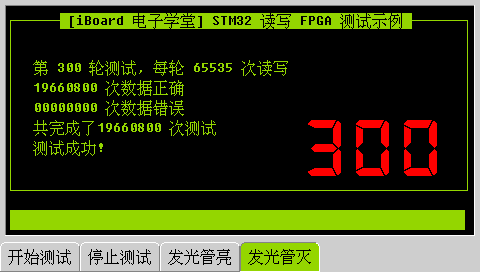
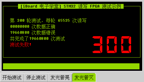
如上图所示,FPGA 内把outh[15..0] 输出的数据,取非后连接到 ina[15..0],ARM程序会写入空间7(也就是outh[15..0]),然后读取空间0(也就是ina[15..0]),然后做数据取非校验,判断成功与否。每轮测试 65536次,共进行300轮测试。核心代码如下:
for (i = 0; i < 65536; i++) {

fpga_write(7, i);

dat = fpga_read(0);

if ((dat + i) != 65535) {

errors++;

}else success++;

}
四、 软件界面
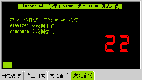
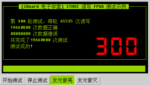
界面包含四个按键,按下【开始测试】则进行读写测试,测试中,按下【停止测试】则停止测试,按下【发光管亮】则FPGA 控制的发光二极管亮,【发光管灭】则FPGA控制的发光二极管灭。
软件包及 PDF 文档下载:
