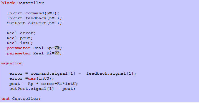
本次调速仿真采用PID调节。首先要确定PID中的各项设计参数,仿真过程中采用临界比例度法确定了大概的Kp值。在若干次调整的过程中,发现加入微分环节后调整时间略有上升,故采用PI调节。调整参数确定为Kp=75,Ki=22。控制器部分的程序如下图所示。原理图如下
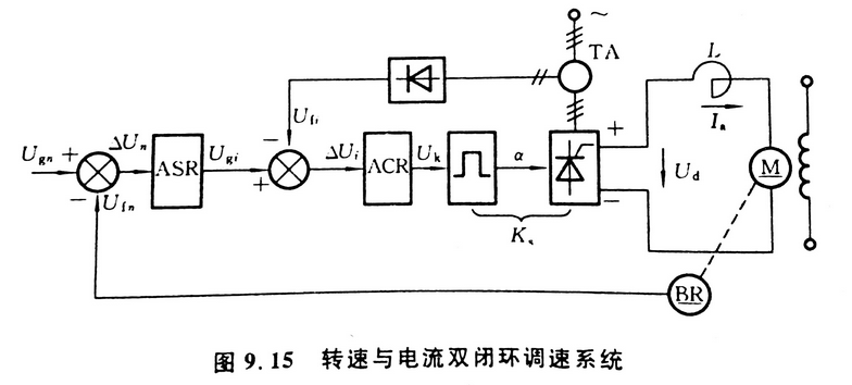
ASR和ACR调节器均使用PI控制器,控制程序如下
电机电流和速度曲线如下图所示
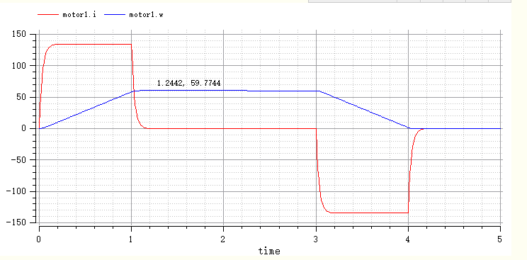
从图中可以看出:电流迅速上升至最大值后不变,然后电机开始匀加速,电流波形明显的改善。电机速度稳定,稳态偏差基本为零。Kp值越大,电流越快上升至最大值,ki值对波形影响不是很大,故选定Kp=75,ki=22。
全部代码如下
type ElectricPotential     = Real;
type ElectricCurrent     = Real(quantity = "ElectricCurrent", unit = "A");
type Resistance       = Real(quantity = "Resistance", unit = "Ohm", min = 0);
type Inductance       = Real(quantity = "Inductance", unit = "H", min = 0);
type Voltage         = ElectricPotential;
type Current         = ElectricCurrent;

type Force           = Real(quantity = "Force", unit = "N");
type Angle           = Real(quantity = "Angle", unit = "rad", displayUnit = "deg");
type Torque         = Real(quantity = "Torque", unit = "N.m");
type AngularVelocity     = Real(quantity = "AngularVelocity", unit = "rad/s", displayUnit = "rev/min");
type AngularAcceleration   = Real(quantity = "AngularAcceleration", unit = "rad/s2");
type MomentOfInertia     = Real(quantity = "MomentOfInertia", unit = "kg.m2");

type Time = Real (final quantity="Time", final unit="s");

connector RotFlange_a       "1D rotational flange (filled square)"
   Angle phi           "Absolute rotational angle of flange";
   flow Torque tau         "Torque in the flange";
end RotFlange_a;        //From Modelica.Mechanical.Rotational.Interfaces

connector RotFlange_b       "1D rotational flange (filled square)"
   Angle phi           "Absolute rotational angle of flange";
   flow Torque tau         "Torque in the flange";
end RotFlange_b;        //From Modelica.Mechanical.Rotational.Interfaces

connector Pin           "Pin of an electrical component"
   Voltage v           "Potential at the pin";
   flow Current i         "Current flowing into the pin";
end Pin;              //From Modelica.Electrical.Analog.Interfaces

connector PositivePin       "Positive pin of an electrical component"
   Voltage v           "Potential at the pin";
   flow Current i         "Current flowing into the pin";
end PositivePin;          //From Modelica.Electrical.Analog.Interfaces

connector NegativePin       "Negative pin of an electrical component"
   Voltage v           "Potential at the pin";
   flow Current i         "Current flowing into the pin";
end NegativePin;          //From Modelica.Electrical.Analog.Interfaces


connector InPort        "Connector with input signals of type Real"
  parameter Integer n = 1    "Dimension of signal vector";
  input Real     signal[n]  "Real input signals";
end InPort;            // From Modelica.Blocks.Interfaces

connector OutPort        "Connector with output signals of type Real"
  parameter Integer n = 1    "Dimension of signal vector";
  output Real     signal[n]  "Real output signals";
end OutPort;          // From Modelica.Blocks.Interfaces


partial model Rigid           // Rotational class Rigid
           "Base class for the rigid connection of two rotational 1D flanges"
  Angle phi               "Absolute rotation angle of component";
  RotFlange_a rotFlange_a  "(left) driving flange (axis directed into plane)";
  RotFlange_b rotFlange_b  "(right) driven flange (axis directed out of plane)";
equation
  rotFlange_a.phi = phi;
  rotFlange_b.phi = phi;
end Rigid;                // From Modelica.Mechanics.Rotational.Interfaces

model Inertia    "1D rotational component with inertia"
  extends Rigid;
  parameter MomentOfInertia J = 1    "Moment of inertia";
  AngularVelocity     w          "Absolute angular velocity of component";
  AngularAcceleration a          "Absolute angular acceleration of component";
equation
  w = der(phi);
  a = der(w);
  J*a = rotFlange_a.tau + rotFlange_b.tau;
end Inertia;              //From Modelica.Mechanics.Rotational

partial model TwoPin          // Same as OnePort in Modelica.Electrical.Analog.Interfaces
                    "Component with two electrical pins p and n and current i from p to n"
  Voltage v                "Voltage drop between the two pins (= p.v - n.v)";
  Current i                "Current flowing from pin p to pin n";
  PositivePin p;
  NegativePin n;
equation
  v = p.v - n.v;
  0 = p.i + n.i;
  i = p.i;
end TwoPin;

model DCMotor                 "DC Motor"
  extends TwoPin;
  extends Rigid;
  OutPort SensorVelocity(n=1);
  OutPort SensorCurrent(n=1);
  parameter MomentOfInertia J"Total Inertia";
  parameter Resistance R"Armature Resistance";
  parameter Inductance L"Armature Inductance";

  parameter Real Kt"Torque Constant";
  parameter Real Ke"EMF Constant";


  AngularVelocity    w          "Angular velocity of motor";
  AngularAcceleration a          "Absolute angular acceleration of motor";
  Torque tau_motor;
  RotFlange_b    rotFlange_b;    // Rotational Flange_b

equation

  w = der(rotFlange_b.phi);
  a = der(w);
  v = R*i+Ke*w+L*der(i);
  tau_motor =  Kt*i;
  J*a = tau_motor + rotFlange_b.tau;
  SensorVelocity.signal[1] = w;
  SensorCurrent.signal[1] =i;
end DCMotor;


class Resistor               "Ideal linear electrical Resistor"
  extends TwoPin;            // Same as OnePort
  parameter Real R(unit = "Ohm")     "Resistance";
equation
  R*i = v;
end Resistor;                // From Modelica.Electrical.Analog.Basic

class Inductor               "Ideal linear electrical Inductor"
  extends TwoPin;            // Same as OnePort
  parameter Real L(unit = "H")       "Inductance";
equation
  v = L*der(i);
end Inductor;              // From Modelica.Electrical.Analog.Basic

class Ground               "Ground node"
  Pin p;
equation
  p.v = 0;
end Ground;                // From Modelica.Electrical.Analog.Basic

model PWMVoltageSource
  extends TwoPin;
  InPort Command(n=1);

  parameter Time T = 0.003;
  parameter Voltage Vin = 200;

equation

  T*der(v)+ v = Vin*Command.signal[1]/10;


end PWMVoltageSource;

block Controller

  InPort command(n=1);
  InPort feedback(n=1);
  OutPort outPort(n=1);

  Real error;
  Real pout;
  Real intU;
  parameter Real Kp=70;
  parameter Real Ki=20;

equation

   error = command.signal[1] -  feedback.signal[1];
   error =der(intU);
   pout = Kp * error+Ki*intU;
   outPort.signal[1] = pout;

end Controller;

block CommandSignalGenerator

  OutPort outPort(n=1);
  Real acc;

equation

   if time <= 1 then
     acc =60;
   elseif time <3 then
     acc = 0;
   elseif time <4 then
     acc = -60;
   else
     acc = 0;
   end if;

   der(outPort.signal[1]) = acc;

end CommandSignalGenerator;


 model DCMotorControlSystem

  Ground       ground1;
  Inertia      inertia1(J = 3, w(fixed = true));
  DCMotor      motor1(J = 1,R = 0.6,L = 0.01,Kt=1.8, Ke=1.8,rotFlange_b(phi(fixed = true)));
  CommandSignalGenerator  sg1;
  Controller   con1;
  Controller   con2;
  PWMVoltageSource PowerSource1;
equation
  connect(sg1.outPort, con1.command);
  connect(con1.feedback, motor1.SensorVelocity);
  connect(con1.outPort, con2.command);
  connect(motor1.SensorCurrent,con2.feedback);
  connect(con2.outPort, PowerSource1.Command);
  connect(PowerSource1.p, motor1.p);
  connect(motor1.rotFlange_b, inertia1.rotFlange_a);
  connect(PowerSource1.n, ground1.p);
  connect(ground1.p, motor1.n);

end DCMotorControlSystem;