Managing Interfaces
Vivado HLS supports two solutions for specifying the type of I/O protocol used:
• Interface Synthesis, where the port interface is created based on efficient industry
standard interfaces.
• Manual interface specification where the interface behavior is explicitly described in
the input source code. This allows any arbitrary I/O protocol to be used.
Interface Synthesis
1 #include "sum_io.h"
2 dout_t sum_io(din_t in1, din_t in2, dio_t *sum) {
3 dout_t temp;
4 *sum = in1 + in2 + *sum;
5 temp = in1 + in2;
6 return
7 temp;
8 }
This example above includes:
• Two pass-by-value inputs in1 and in2.
• A pointer sum that is both read from and written to.
• A function return, the value of temp.
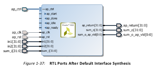
Vivado HLS creates three types of ports on the RTL design:
• Clock and Reset ports: ap_clk and ap_rst.
• Block-Level interface protocol. These are shown expanded in the preceding figure:
ap_start, ap_done, ap_ready, and ap_idle.
• Port Level interface protocols. These are created for each argument in the top-level
function and the function return (if the function returns a value). In this example, these
ports are: in1, in2, sum_i, sum_o, sum_o_ap_vld, and ap_return.
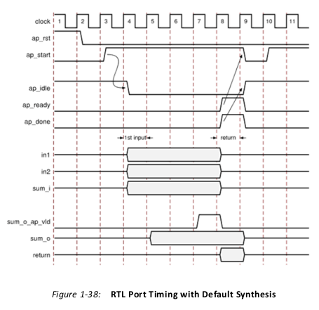
• The design starts when ap_start is asserted High.
• The ap_idle signal is asserted Low to indicate the design is operating.
• The input data is read at any clock after the first cycle. Vivado HLS schedules when the
reads occur. The ap_ready signal is asserted high when all inputs have been read.
• When output sum is calculated, the associated output handshake (sum_o_ap_vld)
indicates that the data is valid.
• When the function completes, ap_done is asserted. This also indicates that the data on
ap_return is valid.
• Port ap_idle is asserted High to indicate that the design is waiting start again.
Clock and Reset Ports
Block-Level Interface Protocol
By default, a block-level interface protocol is added to the design. These signal control the
block, independently of any port-level I/O protocols. These ports control when the block
can start processing data (ap_start), indicate when it is ready to accept new inputs
(ap_ready) and indicate if the design is idle (ap_idle) or has completed operation
(ap_done).
Port-Level Interface Protocol
The I/O protocol created depends on the type
of C argument and on the default. After the block-level protocol has been used to start the operation of the
block, the port-level IO protocols are used to sequence data into and out of the block.
By default input pass-by-value arguments and pointers are implemented as simple wire
ports with no associated handshaking signal. In the above example, the input ports are
therefore implemented without an I/O protocol, only a data port. If the port has no I/O
protocol, (by default or by design) the input data must be held stable until it is read.
By default output pointers are implemented with an associated output valid signal to
indicate when the output data is valid. In the above example, the output port is
implemented with an associated output valid port (sum_o_ap_vld) which indicates when the
data on the port is valid and can be read. If there is no I/O protocol associated with the
output port, it is difficult to know when to read the data. It is always a good idea to use an
I/O protocol on an output.
Function arguments which are both read from and writes to are split into separate input and
output ports. In the above example, sum is implemented as input port sum_i and output
port sum_o with associated I/O protocol port sum_o_ap_vld.
If the function has a return value, an output port ap_return is implemented to provide the
return value. When the design completes one transaction - this is equivalent to one
execution of the C function - the block-level protocols indicate the function is complete
with the ap_done signal. This also indicates the data on port ap_return is valid and can
be read.
Interface Synthesis I/O Protocols
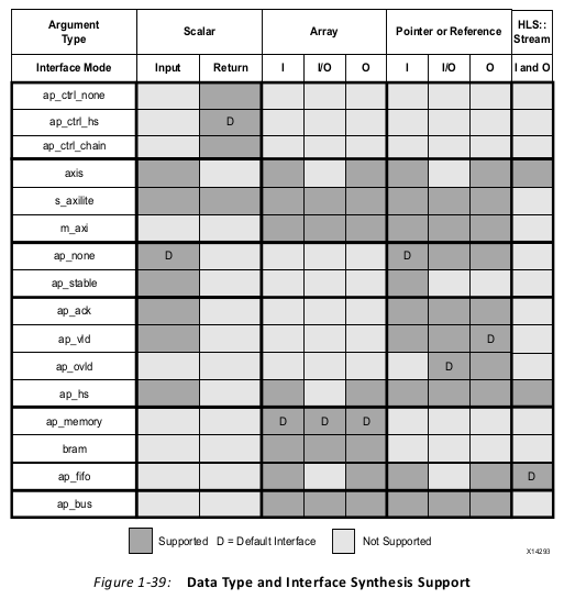
The type of interfaces that are created by interface synthesis depend on the type of C
argument, the default interface mode, and the INTERFACE optimization directive. The
following figure shows the interface protocol mode you can specify on each type of C
argument. This figure uses the following abbreviations:
•D: Default interface mode for each type.
• I: Input arguments, which are only read.
• O: Output arguments, which are only written to.
• I/O: Input/Output arguments, which are both read and written.
Block-Level Interface Protocols
Vivado HLS uses the interface types ap_ctrl_none, ap_ctrl_hs, and ap_ctrl_chain
to specify whether the RTL is implemented with block-level handshake signals. Block-level
handshake signals specify the following:
• When the design can start to perform the operation
• When the operation ends
• When the design is idle and ready for new inputs
You can specify these block-level I/O protocols on the function or the function return. If the
C code does not return a value, you can still specify the block-level I/O protocol on the
function return.
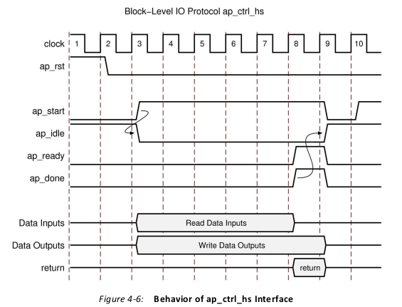
After reset, the following occurs:
1. The block waits for ap_start to go High before it begins operation.
2. Output ap_idle goes Low immediately to indicate the design is no longer idle.
3. The ap_start signal must remain High until ap_ready goes High. Once ap_ready
goes High:
° If ap_start remains High the design will start the next transaction.
° If ap_start is taken Low, the design will complete the current transaction and halt
operation.
4. Data can be read on the input ports.
Note: The input ports can use a port-level I/O protocol that is independent of this block-level
I/O protocol. For details, see Port-Level I/O Protocols.
5. Data can be written to the output ports.
Note: The output ports can use a port-level I/O protocol that is independent of this block-level
I/O protocol. For details, see Port-Level I/O Protocols.
6. Output ap_done goes High when the block completes operation.
Note: If there is an ap_return port, the data on this port is valid when ap_done is High.
Therefore, the ap_done signal also indicates when the data on output ap_return is valid.
7. When the design is ready to accept new inputs, the ap_ready signal goes High.
Following is additional information about the ap_ready signal:
° The ap_ready signal is inactive until the design starts operation.
° In non-pipelined designs, the ap_ready signal is asserted at the same time as
ap_done.
° In pipelined designs, the ap_ready signal might go High at any cycle after
ap_start is sampled High. This depends on how the design is pipelined.
° If the ap_start signal is Low when ap_ready is High, the design executes until
ap_done is High and then stops operation.
° If the ap_start signal is High when ap_ready is High, the next transaction starts
immediately, and the design continues to operate.
8. The ap_idle signal indicates when the design is idle and not operating. Following is
additional information about the ap_idle signal:
° If the ap_start signal is Low when ap_ready is High, the design stops operation,
and the ap_idle signal goes High one cycle after ap_done.
° If the ap_start signal is High when ap_ready is High, the design continues to
operate, and the ap_idle signal remains Low.
Port-Level Interface Protocols: AXI4 Interfaces
• AXI4-Stream interface: Specify on input arguments or output arguments only, not on
input/output arguments.
• AXI4-Lite interface: Specify on any type of argument except arrays. You can group
multiple arguments into the same AXI4-Lite interface.
• AXI4 master interface: Specify on arrays and pointers(and references in C++) only. You
can group multiple arguments into the same AXI4 interface.
Port-Level Interface Protocols: No I/O Protocol
The ap_none and ap_stable modes specify that no I/O protocol be added to the port.
When these modes are specified the argument is implemented as a data port with no other
associated signals. The ap_none mode is the default for scalar inputs. The ap_stable
mode is intended for configuration inputs which only change when the device is in reset
mode.
Port-Level Interface Protocols: Wire Handshakes
The ap_hs port-level I/O protocol provides the greatest flexibility in the development
process, allowing both bottom-up and top-down design flows. Two-way handshakes safely
perform all intra-block communication, and manual intervention or assumptions are not
required for correct operation. The ap_hs port-level I/O protocol provides the following
signals:
• Data port
• Acknowledge signal to indicate when data is consumed
• Valid signal to indicate when data is read
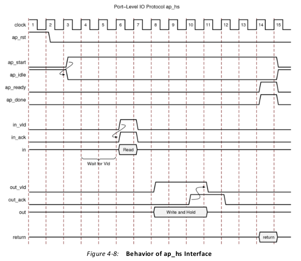
For inputs, the following occurs:
• After start is applied, the block begins normal operation.
• If the design is ready for input data but the input valid is Low, the design stalls and
waits for the input valid to be asserted to indicate a new input value is present.
Note: The preceding figure shows this behavior. In this example, the design is ready to read data
input in on clock cycle 4 and stalls waiting for the input valid before reading the data.
•
When the input valid is asserted High, an output acknowledge is asserted High to
indicate the data was read.
For outputs, the following occurs:
• After start is applied, the block begins normal operation.
• When an output port is written to, its associated output valid signal is simultaneously
asserted to indicate valid data is present on the port.
• If the associated input acknowledge is Low, the design stalls and waits for the input
acknowledge to be asserted.
• When the input acknowledge is asserted, the output valid is deasserted on the next
clock edge.
Port-Level Interface Protocols: Memory Interfaces
ap_memory, bram
The ap_memory and bram interface port-level I/O protocols are used to implement array
arguments. This type of port-level I/O protocol can communicate with memory elements
(for example, RAMs and ROMs) when the implementation requires random accesses to the
memory address locations.
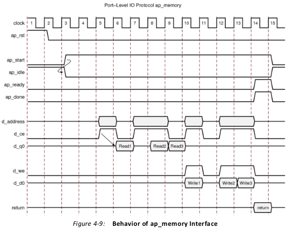
After reset, the following occurs:
• After start is applied, the block begins normal operation.
• Reads are performed by applying an address on the output address ports while
asserting the output signal d_ce.
Note: For a default block RAM, the design expects the input data d_q0 to be available in the
next clock cycle. You can use the RESOURCE directive to indicate the RAM has a longer read
latency.
•
Write operations are performed by asserting output ports d_ce and d_we while
simultaneously applying the address and output data d_d0.
ap_fifo
An ap_fifo interface is the most hardware-efficient approach when the design requires
access to a memory element and the access is always performed in a sequential manner,
that is, no random access is required. The ap_fifo port-level I/O protocol supports the
following:
• Allows the port to be connected to a FIFO
• Enables complete, two-way empty-full communication
• Works for arrays, pointers, and pass-by-reference argument types
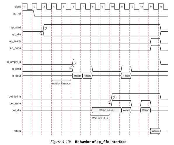
For inputs, the following occurs:
• After start is applied, the block begins normal operation.
• If the input port is ready to be read but the FIFO is empty as indicated by input port
in_empty_n Low, the design stalls and waits for data to become available.
• When the FIFO contains data as indicated by input port in_empty_n High, an output
acknowledge in_read is asserted High to indicate the data was read in this cycle.
For outputs, the following occurs:
• After start is applied, the block begins normal operation.
• If an output port is ready to be written to but the FIFO is full as indicated by
out_full_n Low, the data is placed on the output port but the design stalls and waits
for the space to become available in the FIFO.
• When space becomes available in the FIFO as indicated by out_full_n High, the
output acknowledge signal out_write is asserted to indicate the output data is valid.
• If the top-level function or the top-level loop is pipelined using the -rewind option,
Vivado HLS creates an additional output port with the suffix _lwr. When the last write
to the FIFO interface completes, the _lwr port goes active-High.
Interface Synthesis and Structs
Structs on the interface are by default de-composed into their member elements and ports
are implemented separately for each member element.
Arrays of structs are implemented as multiple arrays, with a separate array for each member
of the struct.
The DATA_PACK optimization directive is used for packing all the elements of a struct into a
single wide vector. This allows all members of the struct to be read and written to
simultaneously.
The single wide-vector created by using the DATA_PACK directive allows more data to be
accessed in a single clock cycle. This is the case when the struct contains an array. When
data can be accessed in a single clock cycle, Vivado HLS automatically unrolls any loops
consuming this data, if doing so improves the throughput. The loop can be fully or partially
unrolled to create enough hardware to consume the additional data in a single clock cycle.
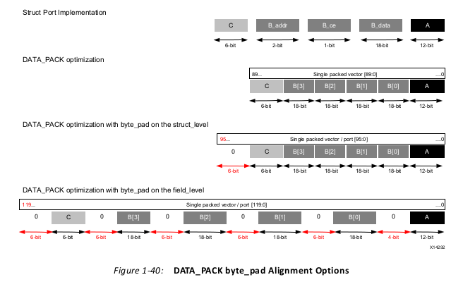
If a struct port using DATA_PACK is to be implemented with an AXI4 interface you may wish
to consider using the DATA_PACK byte_pad option. The byte_pad option is used to
automatically align the member elements to 8-bit boundaries. This alignment is sometimes
required by Xilinx IP.
For the following example code, the options for implementing a struct port are shown in
the following figure.
1 typedef struct{
2 int12 A;
3 int18 B[4];
4 int6 C;
5 } my_data;
6 void foo(my_data *a )
• By default, the members are implemented as individual ports. The array has multiple
ports (data, addr, etc.)
• Using DATA_PACK results in a single wide port.
• Using DATA_PACK with struct_level byte padding aligns entire struct to the next
8-bit boundary.
•Using DATA_PACK with field_level byte padding aligns each struct member to the
next 8-bit boundary.
Interface Synthesis and Multi-Access Pointers
Using pointers which are accessed multiple times can introduce unexpected behavior after
synthesis. In the following example pointer d_i is read four times and pointer d_o is
written to twice: the pointers perform multiple accesses.
 1 #include "pointer_stream_bad.h"
 2 void pointer_stream_bad ( dout_t *d_o,
 3 din_t acc = 0;
 4 acc +=
 5 acc +=
 6 *d_o =
 7 acc +=
 8 acc +=
 9 *d_o =
10 din_t *d_i) {
11 *d_i;
12 *d_i;
13 acc;
14 *d_i;
15 *d_i;
16 acc;
17 }
After synthesis this code will result in an RTL design which reads the input port once and
writes to the output port once. As with any standard C compiler, Vivado HLS will optimize
away the redundant pointer accesses. To implement the above code with the “anticipated”
4 reads on d_i and 2 writes to the d_o the pointers must be specified as volatile as
shown in the next example.
 1 #include "pointer_stream_better.h"
 2 void pointer_stream_better ( volatile dout_t *d_o,
 3 din_t acc = 0;
 4 acc +=
 5 acc +=
 6 *d_o =
 7 acc +=
 8 acc +=
 9 *d_o =
10 volatile din_t *d_i) {
11 *d_i;
12 *d_i;
13 acc;
14 *d_i;
15 *d_i;
16 acc;
17 }
How AXI Works
• Productivity: By standardizing on the AXI interface, developers need to learn only a single protocol for IP.
• Flexibility: Providing the right protocol for the application:
°AXI4 is for memory-mapped interfaces and allows high throughput bursts of up to
256 data transfer cycles with just a single address phase.
°AXI4-Lite is a light-weight, single transaction memory-mapped interface. It has a
small logic footprint and is a simple interface to work with both in design and usage.
°AXI4-Stream removes the requirement for an address phase altogether and allows
unlimited data burst size. AXI4-Stream interfaces and transfers do not have address
phases and are therefore not considered to be memory-mapped.
•Availability: By moving to an industry-standard, you have access not only to the Vivado IP Catalog, but also to a worldwide community of ARM partners.
°Many IP providers support the AXI protocol.
The AXI specifications describe an interface between a single AXI master and AXI slave,
representing IP cores that exchange information with each other. Multiple memory-mapped
AXI masters and slaves can be connected together using AXI infrastructure IP blocks.
The AXI Interconnect is architected using a traditional, monolithic crossbar approach;
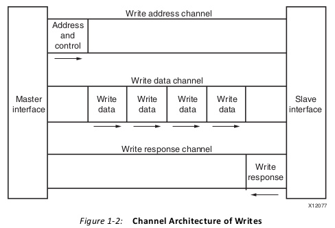
Both AXI4 and AXI4-Lite interfaces consist of five different channels:
• Read Address Channel
• Write Address Channel
• Read Data Channel
• Write Data Channel
• Write Response Channel
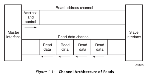
Data can move in both directions between the master and slave simultaneously, and data
transfer sizes can vary. The limit in AXI4 is a burst transaction of up to 256 data transfers.
AXI4-Lite allows only one data transfer per transaction.
AXI4:
• Provides separate data and address connections for reads and writes, which allows
simultaneous, bidirectional data transfer.
• Requires a single address and then bursts up to 256 words of data.
The AXI4 protocol describes options that allow AXI4-compliant systems to achieve very
high data throughput. Some of these features, in addition to bursting, are: data upsizing
and downsizing, multiple outstanding addresses, and out-of-order transaction processing.
At a hardware level, AXI4 allows systems to be built with a different clock for each AXI
master-slave pair. In addition, the AXI4 protocol allows the insertion of register slices (often
called pipeline stages) to aid in timing closure.
AXI4-Lite is similar to AXI4 with some exceptions: The most notable exception is that
bursting is not supported.
The AXI4-Stream protocol defines a single channel for transmission of streaming data. The
AXI4-Stream channel models the write data channel of AXI4. Unlike AXI4, AXI4-Stream
interfaces can burst an unlimited amount of data.You can split, merge, interleave, upsize, and downsize AXI4-Stream
compliant interfaces.
•Memory-Mapped Protocols: In memory-mapped protocols (AXI3, AXI4, and
AXI4-Lite), all transactions involve the concept of transferring a target address within a
system memory space and data.
Memory-mapped systems often provide a more homogeneous way to view the system,
because the IP operates around a defined memory map.
•AXI4-Stream Protocol: Use the AXI4-Stream protocol for applications that typically
focus on a data-centric and data-flow paradigm where the concept of an address is not
present or not required. Each AXI4-Stream acts as a single unidirectional channel with a
handshaking data flow.
At this lower level of operation (compared to the memory-mapped protocol types), the
mechanism to move data between IP is defined and efficient, but there is no unifying
address context between IP. The AXI4-Stream IP can be better optimized for
performance in data flow applications, but also tends to be more specialized around a
given application space.
•Infrastructure IP: An infrastructure IP is a building block used to help assemble
systems. Infrastructure IP tends to be a generic IP that moves or transforms data
around the system using general-purpose AXI4 interfaces and does not interpret data.
Examples of infrastructure IP are:
° AXI Register slices (for pipelining)
° AXI FIFOs (for buffering/clock conversion)
° AXI Interconnect IP and AXI SmartConnect IP (for connecting memory-mapped IP
together)
° AXI Direct Memory Access (DMA) engines (for memory-mapped to stream
conversion)
° AXI Performance Monitors and Protocol Checkers (for analysis and debug)
° AXI Verification IP (for simulation-based verification and performance analysis)
These IP are useful for connecting IP together into a system, but are not generally
endpoints for data.
AXI4 Protocols
AXI4-Stream
About the axi4 stream:
The interface can be used to connect a single master, that generates data, to a
single slave, that receives data. The protocol can also be used when connecting larger numbers
of master and slave components. The protocol supports multiple data streams using the same set
of shared wires, allowing a generic interconnect to be constructed that can perform upsizing,
downsizing and routing operations.
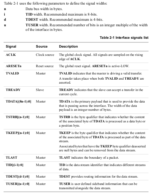
The following stream terms are used in this specification:
Transfer
A single transfer of data across an AXI4-Stream interface. A single transfer is
defined by a single TVALID, TREADY handshake.
Packet
A group of bytes that are transported together across an AXI4-Stream interface.
A packet is similar to an AXI4 burst. A packet may consist of a single transfer or
multiple transfers. Infrastructure components can use packets to deal more
efficiently with a stream in packet-sized groups.
Frame
The highest level of byte grouping in an AXI4-Stream. A frame contains an
integer number of packets. A frame can be a very large number of bytes, for
example an entire video frame buffer.
Data Stream
The transport of data from one source to one destination.
A data stream can be:
•a series of individual byte transfers
•a series of byte transfers grouped together in packets.
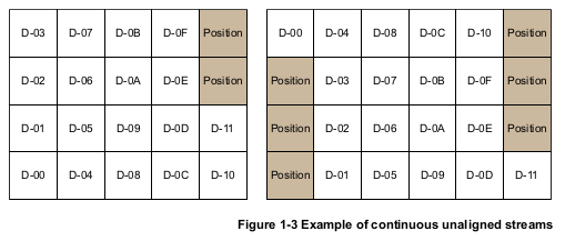
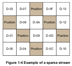
Some examples of different data stream styles that might use the defined AXI4-Stream byte types
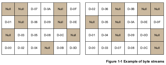
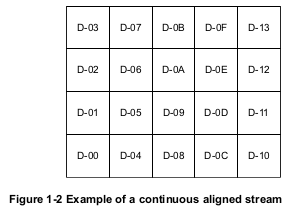
Interface signals:
Using AXI4 Interfaces
AXI4-Stream Interfaces
An AXI4-Stream interface can be applied to any input argument and any array or pointer
output argument. Since an AXI4-Stream interface transfers data in a sequential streaming
manner it cannot be used with arguments which are both read and written. An AXI4-Stream
interface is always sign-extended to the next byte. For example, a 12-bit data value is sign-extended to 16-bit.
There are two basic ways to use an AXI4-Stream in your design.
• Use an AXI4-Stream without side-channels.
• Use an AXI4-Stream with side-channels.
This second use model provides additional functionality, allowing the optional
side-channels which are part of the AXI4-Stream standard, to be used directly in the C code.
AXI4-Stream Interfaces without Side-Channels
An AXI4-Stream is used without side-channels when the function argument does not
contain any AXI4 side-channel elements.
1 void example(int A[50], int B[50]) {
2 //Set the HLS native interface types
3 #pragma HLS INTERFACE axis port=A
4 #pragma HLS INTERFACE axis port=B
5 int i;
6 for(i = 0; i < 50; i++){
7 B[i] = A[i] + 5;
8 }
9 }

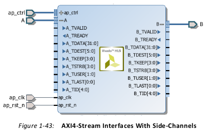
AXI4-Stream Interfaces with Side-Channels
Side-channels are optional signals which are part of the AXI4-Stream standard. The
side-channel signals may be directly referenced and controlled in the C code using a struct,
provided the member elements of the struct match the names of the AXI4-Stream side-channel signals.
An example of this is provided with Vivado
HLS. The Vivado HLS include directory contains the file ap_axi_sdata.h. This header
file contains the following structs:
 1 #include "ap_int.h"
 2 template<int D,int U,int TI,int TD>
 3 struct ap_axis{
 4 ap_int<D> data;
 5 ap_uint<D/8> keep;
 6 ap_uint<D/8> strb;
 7 ap_uint<U> user;
 8 ap_uint<1> last;
 9 ap_uint<TI> id;
10 ap_uint<TD> dest;
11 };
12 template<int D,int U,int TI,int TD>
13 struct ap_axiu{
14 ap_uint<D> data;
15 ap_uint<D/8> keep;
16 ap_uint<D/8> strb;
17 ap_uint<U> user;
18 ap_uint<1> last;
19 ap_uint<TI> id;
20 ap_uint<TD> dest;
21 };
The following example shows how the side-channels can be used directly in the C code and
implemented on the interface. In this example a signed 32-bit data type is used.
 1 #include "ap_axi_sdata.h"
 2 void example(ap_axis<32,2,5,6> A[50], ap_axis<32,2,5,6> B[50]){
 3 //Map ports to Vivado HLS interfaces
 4 #pragma HLS INTERFACE axis port=A
 5 #pragma HLS INTERFACE axis port=B
 6 int i;
 7 for(i = 0; i < 50; i++){
 8 B[i].data = A[i].data.to_int() + 5;
 9 B[i].keep = A[i].keep;
10 B[i].strb = A[i].strb;
11 B[i].user = A[i].user;
12 B[i].last = A[i].last;
13 B[i].id = A[i].id;
14 B[i].dest = A[i].dest;
15 }
16 }
AXI4-Lite Interface
You can use an AXI4-Lite interface to allow the design to be controlled by a CPU or
microcontroller. Using the Vivado HLS AXI4-Lite interface, you can:
• Group multiple ports into the same AXI4-Lite interface.
• Output C driver files for use with the code running on a processor.
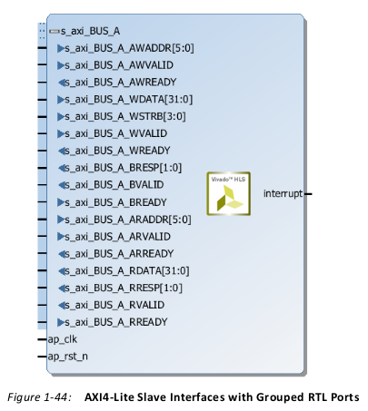
The following example shows how Vivado HLS implements multiple arguments, including
the function return, as an AXI4-Lite interface. Because each directive uses the same name
for the bundle option, each of the ports is grouped into the same AXI4-Lite interface.
 1 void example(char *a,
 2 {
 3 #pragma HLS INTERFACE
 4 #pragma HLS INTERFACE
 5 #pragma HLS INTERFACE
 6 #pragma HLS INTERFACE
 7 #pragma HLS INTERFACE
 8 char *b, char *c)
 9 s_axilite port=return
10 s_axilite port=a
11 s_axilite port=b
12 s_axilite port=c
13 ap_vld port=b
14 bundle=BUS_A
15 bundle=BUS_A
16 bundle=BUS_A
17 bundle=BUS_A offset=0x0400
18 *c += *a + *b;
19 }
By default, Vivado HLS automatically assigns the address for each port that is grouped into
an AXI4-Lite interface. Vivado HLS provides the assigned addresses in the C driver files. To explicitly define the address, you can use the
offset option, as shown for argument c in the example above.
After synthesis, Vivado HLS implements the ports in the AXI4-Lite port, as shown in the
following figure. Vivado HLS creates the interrupt port by including the function return in
the AXI4-Lite interface. You can program the interrupt through the AXI4-Lite interface. You
can also drive the interrupt from the following block-level protocols:
• ap_done: Indicates when the function completes all operations.
• ap_ready: Indicates when the function is ready for new input data.
Control Clock and Reset in AXI4-Lite Interfaces
By default, Vivado HLS uses the same clock for the AXI4-Lite interface and the synthesized
design. Vivado HLS connects all registers in the AXI4-Lite interface to the clock used for the
synthesized logic (ap_clk).
Optionally, you can use the INTERFACE directive clock option to specify a separate clock
for each AXI4-Lite port.
- RECOMMENDED: For ease of use during the operation of the design, Xilinx recommends that you do not include additional I/O protocols in the ports grouped into an AXI4-Lite interface. However, Xilinx recommends that you include the block-level I/O protocol associated with the return port in the AXI4-Lite interface.
- IMPORTANT: In an AXI4-Lite interface, Vivado HLS reserves addresses 0x0000 through 0x000C for the block-level I/O protocol signals and interrupt controls.
AXI4 Master Interface
You can use an AXI4 master interface on array or pointer/reference arguments, which
Vivado HLS implements in one of the following modes:
• Individual data transfers
• Burst mode data transfers
With individual data transfers, Vivado HLS reads or writes a single element of data for each
address. The following example shows a single read and single write operation. In this
example, Vivado HLS generates an address on the AXI interface to read a single data value
and an address to write a single data value. The interface transfers one data value per
address.
1 void bus (int *d) {
2 static int acc = 0;
3 acc += *d;
4 *d = acc;
5 }
With burst mode transfers, Vivado HLS reads or writes data using a single base address
followed by multiple sequential data samples, which makes this mode capable of higher
data throughput. Burst mode of operation is possible when you use the C memcpy function
or a pipelined for loop.
 1 void example(volatile int *a){
 2 #pragma HLS INTERFACE m_axi depth=50 port=a
 3 #pragma HLS INTERFACE s_axilite port=return
 4 //Port a is assigned to an AXI4 master interface
 5 int i;
 6 int buff[50];
 7 //memcpy creates a burst access to memory
 8 memcpy(buff,(const int*)a,50*sizeof(int));
 9 for(i=0; i < 50; i++){
10 buff[i] = buff[i] + 100;
11 }
12 memcpy((int *)a,buff,50*sizeof(int));
13 }
The following example shows the same code as the preceding example but uses a for loop
to copy the data out:
 1 void example(volatile int *a){
 2 #pragma HLS INTERFACE m_axi depth=50 port=a
 3 #pragma HLS INTERFACE s_axilite port=return
 4 //Port a is assigned to an AXI4 master interface
 5 int i;
 6 int buff[50];
 7 //memcpy creates a burst access to memory
 8 memcpy(buff,(const int*)a,50*sizeof(int));
 9 for(i=0; i < 50; i++){
10 buff[i] = buff[i] + 100;
11 }
12 for(i=0; i < 50; i++){
13 #pragma HLS PIPELINE
14 a[i] = buff[i];
15 }
16 }
When using a for loop to implement burst reads or writes, follow these requirements:
• Pipeline the loop
• Access addresses in increasing order
• Do not place accesses inside a conditional statement
• For nested loops, do not flatten loops, because this inhibits the burst operation
In the following example, Vivado HLS implements the port reads as burst transfers. Port a
is specified without using the bundle option and is implemented in the default AXI
interface. Port b is specified using a named bundle and is implemented in a separate AXI
interface called d2_port.
 1 void example(volatile int *a, int *b){
 2 #pragma HLS INTERFACE s_axilite port=return
 3 #pragma HLS INTERFACE m_axi depth=50 port=a
 4 #pragma HLS INTERFACE m_axi depth=50 port=b bundle=d2_port
 5 int i;
 6 int buff[50];
 7 //copy data in
 8 for(i=0; i < 50; i++){
 9 #pragma HLS PIPELINE
10 buff[i] = a[i] + b[i];
11 }
12 ...
13 }
Controlling AXI4 Burst Behavior
An optimal AXI4 interface is one in which the design never stalls while waiting to access the
bus, and after bus access is granted, the bus never stalls while waiting for the design to
read/write. To create the optimal AXI4 interface, the following options are provided in the
INTERFACE directive to specify the behavior of the bursts and optimize the efficiency of the
AXI4 interface.
Some of these options use internal storage to buffer data and may have an impact on area
and resources:
• latency: Specifies the expected latency of the AXI4 interface, allowing the design to
initiate a bus request a number of cycles (latency) before the read or write is expected.
If this figure it too low, the design will be ready too soon and may stall waiting for the
bus. If this figure is too high, bus access may be granted but the bus may stall waiting
on the design to start the access.
• max_read_burst_length: Specifies the maximum number of data values read
during a burst transfer.
• num_read_outstanding: Specifies how many read requests can be made to the AXI4
bus, without a response, before the design stalls. This implies internal storage in the
design, a FIFO of size:
num_read_outstanding*max_read_burst_length*word_size.
• max_write_burst_length: Specifies the maximum number of data values written
during a burst transfer.
•num_write_outstanding: Specifies how many write requests can be made to the
AXI4 bus, without a response, before the design stalls. This implies internal storage in
the design, a FIFO of size:
num_read_outstanding*max_read_burst_length*word_size
The following example can be used to help explain these options:
1 #pragma HLS interface m_axi port=input offset=slave bundle=gmem0
2 depth=1024*1024*16/(512/8)
3 latency=100
4 num_read_outstanding=32
5 num_write_outstanding=32
6 max_read_burst_length=16
7 max_write_burst_length=16
The interface is specified as having a latency of 100. Vivado HLS seeks to schedule the
request for burst access 100 clock cycles before the design is ready to access the AXI4 bus.
To further improve bus efficiency, the options num_write_outstanding and
num_read_outstanding ensure the design contains enough buffering to store up to 32
read and write accesses. This allows the design to continue processing until the bus
requests are serviced. Finally, the options max_read_burst_length and
max_write_burst_length ensure the maximum burst size is 16 and that the AXI4
interface does not hold the bus for longer than this.
Controlling the Address Offset in an AXI4 Interface
By default, the AXI4 master interface starts all read and write operations from address
0x00000000. For example, given the following code, the design reads data from addresses
0x00000000 to 0x000000c7 (50 32-bit words, gives 200 bytes), which represents 50 address
values. The design then writes data back to the same addresses.
 1 void example(volatile int *a){
 2 #pragma HLS INTERFACE m_axi depth=50 port=a
 3 #pragma HLS INTERFACE s_axilite port=return bundle=AXILiteS
 4 int i;
 5 int buff[50];
 6 memcpy(buff,(const int*)a,50*sizeof(int));
 7 for(i=0; i < 50; i++){
 8 buff[i] = buff[i] + 100;
 9 }
10 memcpy((int *)a,buff,50*sizeof(int));
11 }
To apply an address offset, use the -offset option with the INTERFACE directive, and
specify one of the following options:
• off: Does not apply an offset address. This is the default.
• direct: Adds a 32-bit port to the design for applying an address offset.
• slave: Adds a 32-bit register inside the AXI4-Lite interface for applying an address
offset.
If you use the slave option in an AXI interface, you must use an AXI4-Lite port on the
design interface. Xilinx recommends that you implement the AXI4-Lite interface using the
following pragma:
#pragma HLS INTERFACE s_axilite port=return
In addition, if you use the slave option and you used several AXI4-Lite interfaces, you
must ensure that the AXI master port offset register is bundled into the correct AXI4-Lite
interface. In the following example, port a is implemented as an AXI master interface with
an offset and AXI4-Lite interfaces called AXI_Lite_1 and AXI_Lite_2:
#pragma HLS INTERFACE m_axi port=a depth=50 offset=slave
#pragma HLS INTERFACE s_axilite port=return bundle=AXI_Lite_1
#pragma HLS INTERFACE s_axilite port=b bundle=AXI_Lite_2
The following INTERFACE directive is required to ensure that the offset register for port a is
bundled into the AXI4-Lite interface called AXI_Lite_1:
#pragma HLS INTERFACE s_axilite port=a bundle=AXI_Lite_1
Reference
1. Xinlinx UG902
2. Xilinx UG1037, Vivado Design Suite AXI Reference Guide
3. AMBA 4 AXI4-Stream Protocol: https://static.docs.arm.com/ihi0051/a/IHI0051A_amba4_axi4_stream_v1_0_protocol_spec.pdf