一:项目介绍
该项目最终实现的功能很简单,手指在触摸屏左滑(下一张图片),右滑(上一张图片)
1.1软硬件资源
硬件:pc机,ARM Cortex-A9开发板
软件:linux 操作系统
1.3项目流程
本项目主要分为三大模块:
一:LCD驱动编写
二:I2C驱动编写
三:使用I2C读取触摸屏上的数据,判断是向左或者向右,再控制lcd进行图片的显示
大体流程图如下所示: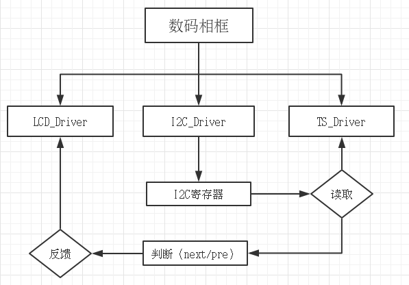
二:项目环境搭建
2.1安装交叉环境编译器 4.5.1,dnw软件
2.2烧写uboot
三:LCD裸板驱动的编写
在编写lcd驱动前先看一下电路图:
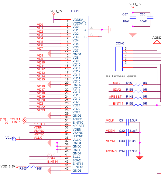
可以观察到 LCD1由45根线来控制,主要配置的寄存器是24根RGB以及TOU1 EINT10 以及VDEN VYNC HSYNC VCLK驱动;
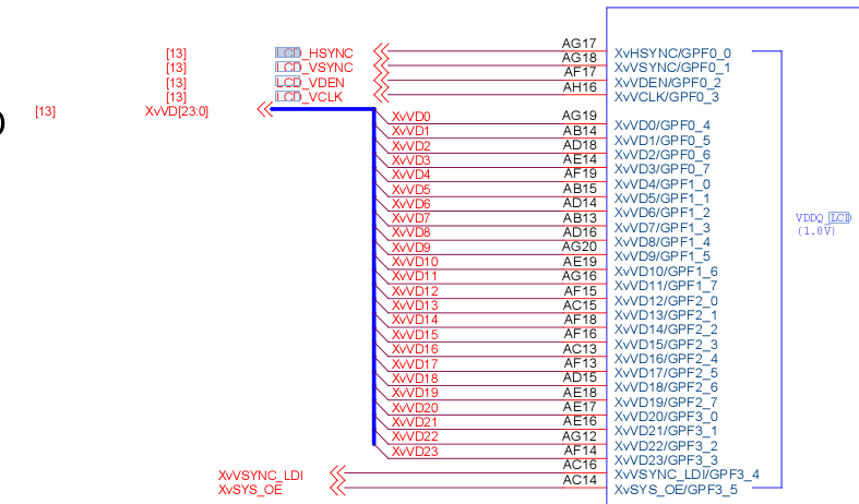
在核心板中找到网标,找出相应的寄存器;
编写lcd可大致分为如下几步:
第一步:配置 OUT1 EINT10 以及24根RGB
第二步:看时序图配置相关寄存器
第三步:配置窗口寄存器
3.1 lcd控制器
Exynos4412的LCD控制器可以通过编程支持不同LCD屏的要求,例如行和列像素数,数据总线宽度,接口时序和刷新频率等。
LCD控制器的主要作用,是将定位在系统存储器中的显示缓冲区中的LCD图像数据传送到外部LCD驱动器,并产生必要的控制信号,
例如RGB_VSYNC,RGB_HSYNC, RGB_VCLK等
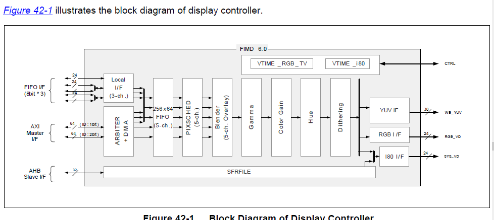
由上图可知:LCD控制器的构成主要由VSFR,VDMA,VPRCS , VTIME和视频时钟产生器几个模块组成;
(1)VSFR由121个可编程控制器组,一套gammaLUT寄存器组(包括64个寄存器),一套i80命令寄存器组(包括12个寄存器)和5块256*32调色板存储器组成,主要用于对lcd控制器进行配置。
(2)VDMA是LCD专用的DMA传输通道,可以自动从系统总线上获取视频数据传送到VPRCS,无需CPU干涉。
(3)VPRCS收到数据后组成特定的格式(如16bpp或24bpp),然后通过数据接口(RGB_VD, VEN_VD, V656_VD or SYS_VD)传送到外部LCD屏上。
(4)VTIME模块由可编程逻辑组成,负责不同lcd驱动器的接口时序控制需求。VTIME模块产生 RGB_VSYNC, RGB_HSYNC, RGB_VCLK, RGB_VDEN,VEN_VSYNC等信号。
3.2 lcd接口信号
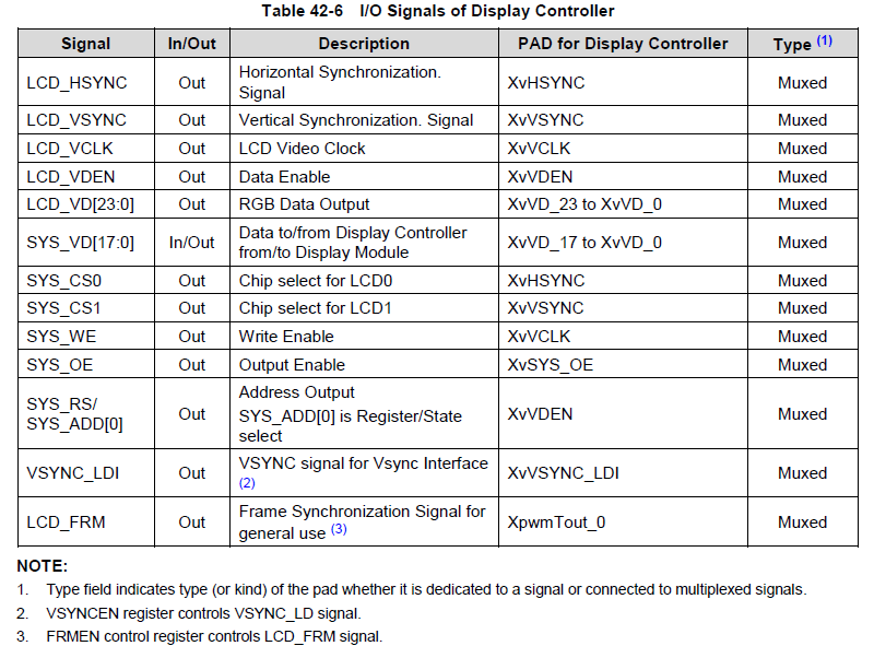
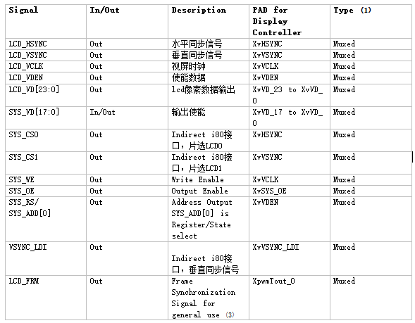
其中主要的RGB接口信号:
(1)LCD_HSYNC:行同步信号,表示一行数据的开始,LCD控制器在整个水平线(整行)数据移入LCD驱动器后,插入一个LCD_HSYNC信号;
(2)LCD_VSYNC: 帧同步信号,表示一帧数据的开始,LCD控制器在一个完整帧显示完成后立即插入一个LCD_VSYNC信号,开始新一帧的显示;VSYNC信号出现的频率表示一秒钟内能显示多少帧图像,称为“显示器的频率”
(3)LCD_VCLK:像素时钟信号,表示正在传输一个像素的数据;
(4)LCD_VDEN:数据使能信号;
(5) LCD_VD[23:0]: LCD像素数据输出端口
3.3、RGB信号的时序
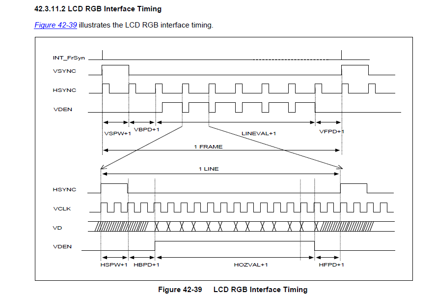
(1)、相关参数说明
VBPD(vertical back porch):表示在一帧图像开始时,垂直同步信号以后的无效的行数。
VFBD(vertical front porch):表示在一帧图像结束后,垂直同步信号以前的无效的行数。
VSPW(vertical sync pulse width):表示垂直同步脉冲的宽度,用行数计算。
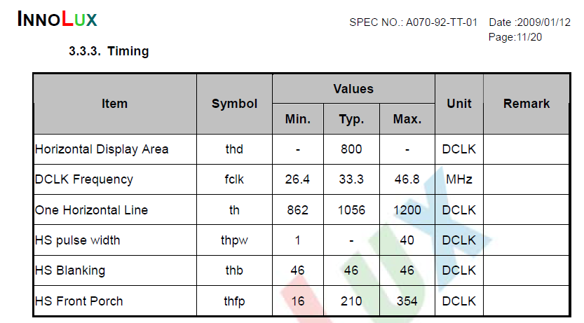
HBPD(horizontal back porch):表示从水平同步信号开始到一行的有效数据开始之间的VCLK的个数。
HFPD(horizontal front porth):表示一行的有效数据结束到下一个水平同步信号开始之间的VCLK的个数。
HSPW(horizontal sync pulse width):表示水平同步信号的宽度,用VCLK计算。
(2)、帧的传输过程
VSYNC信号有效时,表示一帧数据的开始,信号宽度为(VSPW +1)个HSYNC信号周期,即(VSPW +1)个无效行;
VSYNC信号脉冲之后,总共还要经过(VBPD+ 1)个HSYNC信号周期,有效的行数据才出现; 所以,在VSYNC信号有效之后,还要经过(VSPW +1 + VBPD + 1)个无效的行;
随即发出(LINEVAL+ 1)行的有效数据;
最后是(VFPD + 1)个无效的行。
(3)、行中像素数据的传输过程
HSYNC信号有效时,表示一行数据的开始,信号宽度为(HSPW+ 1)个VCLK信号周期,即(HSPW +1)个无效像素;
HSYNC信号脉冲之后,还要经过(HBPD +1)个VCLK信号周期,有效的像素数据才出现;
随后发出(HOZVAL+1)个像素的有效数据;
最后是(HFPD +1)个无效的像素。
(4)、将VSYNC、HSYNC、VCLK等信号的时间参数设置好之后,并将帧内存的地址告诉LCD控制器,它即可自动地发起DMA传输从帧内存中得到图像数据,最终在上述信号的控制下RGB数据出现在数据总线VD[23:0]上。用户只需要把要显示的图像数据写入帧内存中。
3.4、lcd相关寄存器设置说明
(1)设置LCD的RGB接口,只需要将其设置为2即可。同时将其IO口设置成为内部上拉,且将其驱动能力设置为最强代码如下:
GPF0CON = 0x22222222;
GPF1CON = 0x22222222;
GPF2CON = 0x22222222;
GPF3CON &= ~(0xffff);
GPF3CON |= 0x2222;
/*max driver strength*/
GPF0DRV = 0xfffffff;
GPF1DRV = 0xfffffff;
GPF2DRV = 0xfffffff;
GPF3DRV &= ~0xff;
GPF3DRV |= 0xff;
(2)设置LCD相关时钟寄存器
这一步主要设置选择LCD时钟输入源为MPLL,且不对其进行分频,同时设置LCDBLK_CFG使其使用FIMD接口,且设置LCDBLK_CFG2使其PWM输出使能;
(4)设置VIDCONx,设置接口类型,时钟分频,极性以及使能LCD控制器等
VIDCON0:这一个寄存器主要设置接口类型和时钟分频,这里仅仅设置了其时钟分频值,由于我们的MPLL为800MHZ,所以这里设置值,根据手册进行计算,要得到33.3MHZ左右的像素时钟;
VIDCON0 = (1 << 17)|(23 <<6)|3;
VIDCON1:主要设置时钟信号,需不需要翻转,以及触发方式;
VIDTCONx:用来设置时序和长宽等参数,这里就主要设置VBPD(vertical back porch)、 VFBD(vertical frontporch)、VSPW(vertical sync pulse width)、HBPD(horizontal backporch)、 HFPD(horizontal sync pulse width)等参数
VIDTCON0取值过程,VIDTCON0设置帧同步时序。
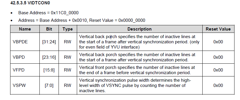
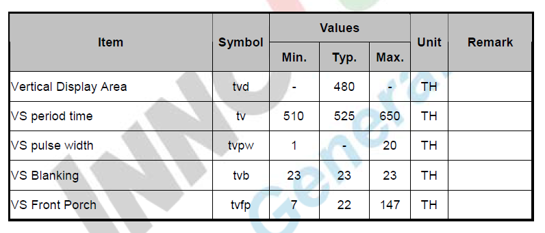
VIDTCON0 = (22 << 16) | (21 << 8) | (0);
VIDTCON1取值过程,VIDTCON1设置像素同步时序。
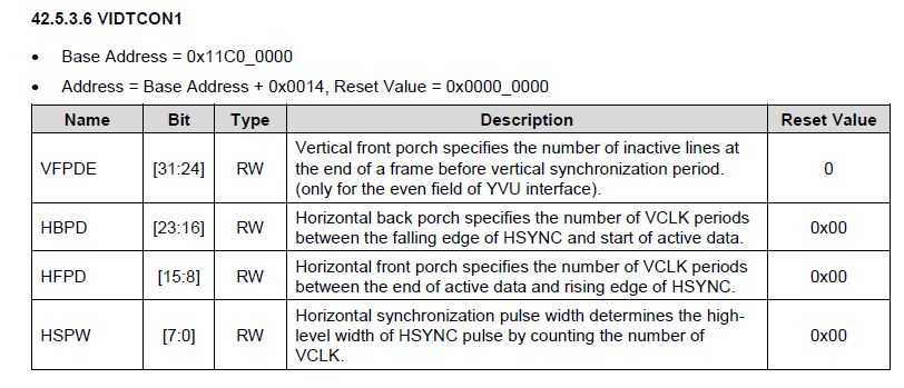
VIDTCON1 = (35 << 16) | (209 << 8) | (9);
VIDTCON2
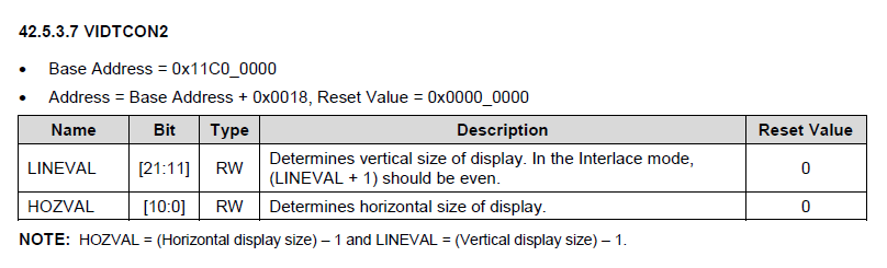
VIDTCON2 = (479 << 11) | 799;
(5)设置WINCON0寄存器,即设置数据格式。
Exynos4412的LCD控制器有overlay功能,它支持5个window。这里只使用window0,设置其代码RGB模式为24bit(A888)且使能window0;
WINCON0 = (1 << 22) | (1 << 15) | (11 << 2) | 1;
(6)设置VID0SD0A/B/C,即设置Window0的坐标系
配置VIDW00ADD0B0和VIDW00ADD1B0,设置framebuffer的地址;
(7)配置SHADOWCON和WINCHMAP2、选择使能DMA通道0。由于我们使用的是Window0,所以需要使能DMA通道0;
(8)最后设置VIDCON0低两位使能LCD
VIDCON0 |= 1 | (1 << 1);
下面是Tiny4412 LCD裸板驱动具体代码:


 1 #define LCD_BASE 0x11C00000
 2
 3 #define VIDCON0     (*(volatile unsigned int *)(LCD_BASE + 0x0000))
 4 #define VIDCON1     (*(volatile unsigned int *)(LCD_BASE + 0x0004))
 5 #define VIDCON2     (*(volatile unsigned int *)(LCD_BASE + 0x0008))
 6 #define VIDCON3     (*(volatile unsigned int *)(LCD_BASE + 0x000C))
 7 #define VIDTCON0     (*(volatile unsigned int *)(LCD_BASE + 0x0010))
 8 #define VIDTCON1     (*(volatile unsigned int *)(LCD_BASE + 0x0014))
 9 #define VIDTCON2     (*(volatile unsigned int *)(LCD_BASE + 0x0018))
10 #define VIDTCON3     (*(volatile unsigned int *)(LCD_BASE + 0x001C))
11 #define WINCON0     (*(volatile unsigned int *)(LCD_BASE + 0x0020))
12 #define WINCON1     (*(volatile unsigned int *)(LCD_BASE + 0x0024))
13 #define WINCON2     (*(volatile unsigned int *)(LCD_BASE + 0x0028))
14 #define WINCON3     (*(volatile unsigned int *)(LCD_BASE + 0x002C))
15 #define WINCON4     (*(volatile unsigned int *)(LCD_BASE + 0x0030))
16 #define SHADOWCON     (*(volatile unsigned int *)(LCD_BASE + 0x0034))
17 #define WINCHMAP2     (*(volatile unsigned int *)(LCD_BASE + 0x003C))
18 #define VIDOSD0A     (*(volatile unsigned int *)(LCD_BASE + 0x0040))
19 #define VIDOSD0B     (*(volatile unsigned int *)(LCD_BASE + 0x0044))
20 #define VIDOSD0C     (*(volatile unsigned int *)(LCD_BASE + 0x0048))
21 #define VIDOSD1A     (*(volatile unsigned int *)(LCD_BASE + 0x0050))
22 #define VIDOSD1B     (*(volatile unsigned int *)(LCD_BASE + 0x0054))
23 #define VIDOSD1C     (*(volatile unsigned int *)(LCD_BASE + 0x0058))
24 #define VIDOSD1D     (*(volatile unsigned int *)(LCD_BASE + 0x005C))
25 #define VIDOSD2A     (*(volatile unsigned int *)(LCD_BASE + 0x0060))
26 #define VIDOSD2B     (*(volatile unsigned int *)(LCD_BASE + 0x0064))
27 #define VIDOSD2C     (*(volatile unsigned int *)(LCD_BASE + 0x0068))
28 #define VIDOSD2D     (*(volatile unsigned int *)(LCD_BASE + 0x006C))
29 #define VIDOSD3A     (*(volatile unsigned int *)(LCD_BASE + 0x0070))
30 #define VIDOSD3B     (*(volatile unsigned int *)(LCD_BASE + 0x0074))
31 #define VIDOSD3C     (*(volatile unsigned int *)(LCD_BASE + 0x0078))
32 #define VIDOSD4A     (*(volatile unsigned int *)(LCD_BASE + 0x0080))
33 #define VIDOSD4B     (*(volatile unsigned int *)(LCD_BASE + 0x0084))
34 #define VIDOSD4C     (*(volatile unsigned int *)(LCD_BASE + 0x0088))
35 #define VIDW00ADD0B0     (*(volatile unsigned int *)(LCD_BASE + 0x00A0))
36 #define VIDW00ADD0B1     (*(volatile unsigned int *)(LCD_BASE + 0x00A4))
37 #define VIDW00ADD0B2     (*(volatile unsigned int *)(LCD_BASE + 0x20A0))
38 #define VIDW01ADD0B0     (*(volatile unsigned int *)(LCD_BASE + 0x00A8))
39 #define VIDW01ADD0B1     (*(volatile unsigned int *)(LCD_BASE + 0x00AC))
40 #define VIDW01ADD0B2     (*(volatile unsigned int *)(LCD_BASE + 0x20A8))
41 #define VIDW02ADD0B0     (*(volatile unsigned int *)(LCD_BASE + 0x00B0))
42 #define VIDW02ADD0B1     (*(volatile unsigned int *)(LCD_BASE + 0x00B4))
43 #define VIDW02ADD0B2     (*(volatile unsigned int *)(LCD_BASE + 0x20B0))
44 #define VIDW03ADD0B0     (*(volatile unsigned int *)(LCD_BASE + 0x00B8))
45 #define VIDW03ADD0B1     (*(volatile unsigned int *)(LCD_BASE + 0x00BC))
46 #define VIDW03ADD0B2     (*(volatile unsigned int *)(LCD_BASE + 0x20B8))
47 #define VIDW04ADD0B0     (*(volatile unsigned int *)(LCD_BASE + 0x00C0))
48 #define VIDW04ADD0B1     (*(volatile unsigned int *)(LCD_BASE + 0x00C4))
49 #define VIDW04ADD0B2     (*(volatile unsigned int *)(LCD_BASE + 0x20C0))
50 #define VIDW00ADD1B0     (*(volatile unsigned int *)(LCD_BASE + 0x00D0))
51 #define VIDW00ADD1B1     (*(volatile unsigned int *)(LCD_BASE + 0x00D4))
52 #define VIDW00ADD1B2     (*(volatile unsigned int *)(LCD_BASE + 0x20D0))
53 #define VIDW01ADD1B0     (*(volatile unsigned int *)(LCD_BASE + 0x00D8))
54 #define VIDW01ADD1B1     (*(volatile unsigned int *)(LCD_BASE + 0x00DC))
55 #define VIDW01ADD1B2     (*(volatile unsigned int *)(LCD_BASE + 0x20D8))
56 #define VIDW02ADD1B0     (*(volatile unsigned int *)(LCD_BASE + 0x00E0))
57 #define VIDW02ADD1B1     (*(volatile unsigned int *)(LCD_BASE + 0x00E4))
58 #define VIDW02ADD1B2     (*(volatile unsigned int *)(LCD_BASE + 0x20E0))
59 #define VIDW03ADD1B0     (*(volatile unsigned int *)(LCD_BASE + 0x00E8))
60 #define VIDW03ADD1B1     (*(volatile unsigned int *)(LCD_BASE + 0x00EC))
61 #define VIDW03ADD1B2     (*(volatile unsigned int *)(LCD_BASE + 0x20E8))
62 #define VIDW04ADD1B0     (*(volatile unsigned int *)(LCD_BASE + 0x00F0))
63 #define VIDW04ADD1B1     (*(volatile unsigned int *)(LCD_BASE + 0x00F4))
64 #define VIDW04ADD1B2     (*(volatile unsigned int *)(LCD_BASE + 0x20F0))
65 #define VIDW00ADD2     (*(volatile unsigned int *)(LCD_BASE + 0x0100))
66 #define VIDW01ADD2     (*(volatile unsigned int *)(LCD_BASE + 0x0104))
67 #define VIDW02ADD2     (*(volatile unsigned int *)(LCD_BASE + 0x0108))
68 #define VIDW03ADD2     (*(volatile unsigned int *)(LCD_BASE + 0x010C))
69 #define VIDW04ADD2     (*(volatile unsigned int *)(LCD_BASE + 0x0110))
70 #define VIDINTCON0     (*(volatile unsigned int *)(LCD_BASE + 0x0130))
71 #define VIDINTCON1     (*(volatile unsigned int *)(LCD_BASE + 0x0134))
72 #define W1KEYCON0     (*(volatile unsigned int *)(LCD_BASE + 0x0140))
73 #define VIDW0ALPHA0     (*(volatile unsigned int *)(LCD_BASE + 0x021C))
74 #define VIDW0ALPHA1     (*(volatile unsigned int *)(LCD_BASE + 0x0220))
75 #define VIDW1ALPHA0     (*(volatile unsigned int *)(LCD_BASE + 0x0224))
76 #define VIDW1ALPHA1     (*(volatile unsigned int *)(LCD_BASE + 0x0228))
77 #define VIDW2ALPHA0     (*(volatile unsigned int *)(LCD_BASE + 0x022C))
78 #define VIDW2ALPHA1     (*(volatile unsigned int *)(LCD_BASE + 0x0230))
79 #define VIDW3ALPHA0     (*(volatile unsigned int *)(LCD_BASE + 0x0234))
80 #define VIDW3ALPHA1     (*(volatile unsigned int *)(LCD_BASE + 0x0238))
81 #define VIDW4ALPHA0     (*(volatile unsigned int *)(LCD_BASE + 0x023C))
82 #define VIDW4ALPHA1     (*(volatile unsigned int *)(LCD_BASE + 0x0240))
83
84 #endif
  1 #include "lcd.h"
  2 #define RGB888(r, g, b) (((r) << 16) | ((g) << 8) | (b))
  3
  4 void lcd_init(void);
  5 void clean_screen(unsigned long *fb, int w, int h);
  6
  7 int main(void)
  8 {
  9      fb = ADDR0;
 10      lcd_init();
 11      clean_screen(fb, 800, 480);
 12 }
 13
 14 void clean_screen(unsigned long *fb, int w, int h)
 15 {
 16      int i, j;
 17      for (i = 0; i < h; i ++) {
 18          for (j = 0; j < w; j ++) {
 19               fb[i * w + j] = RGB888(255, 0, 0);
 20          }
 21      }
 22 }
 23
 24 void lcd_init(void)
 25 {
 26     /*
 27      *<Exyons 4412 datasheet pg138 pg141 pg144 pg147> *
 28      * GPF0CON : [31:0] : 0x2
 29      * GPF1CON : [31:0] : 0x2
 30      * GPF2CON : [31:0] : 0x2
 31      * GPF3CON : [31:0] : 0x2
 32      * */
 33
 34     //定义IO引脚功能为RGB接口
 35     GPF0CON = 0x22222222;
 36     GPF1CON = 0x22222222;
 37     GPF2CON = 0x22222222;
 38     GPF3CON &= ~(0xffff);
 39     GPF3CON |= 0x2222;
 40
 41     //max driver strebgh----
 42     GPF0DRV = 0xffffffff;
 43     GPF1DRV = 0xffffffff;
 44     GPF2DRV = 0xffffffff;
 45     GPF3DRV &= ~0xff;
 46     GPF3DRV |= 0xff;
 47     /*
 48      *<Exyons 4412 datasheet pg526>
 49      *CLK_DIV_LCD:
 50      *          [3:0]:FIMD0_RATIO   0
 51      *              SCLK_FIMD0 = MOUTFIMD0/(FIMD0_RATIO + 1)
 52      *                         = MOUTFIMD0/1 = 800MHz
 53      *              MOUTFIMD0 == SCLKmpll_user_t == 800MHz      <Exyons 4412 datasheet pg453> LCD0_BLK
 54      * */
 55
 56     CLK_DIV_LCD &= ~0xf;
 57     /*
 58      *<Exyons 4412 datasheet pg501>
 59      *CLK_SRC_LCD0:
 60      *          [3:0]:FIMD0_SEL 0110 ===> SCLKmpll_user_t 选择时钟源为SCLKmpll_user_t
 61      *
 62      * */
 63     CLK_SRC_LCD0 &= ~0xf;
 64     CLK_SRC_LCD0 |= 6;
 65     //LCD0_SYS_PWR_REG == 7 Don't use
 66
 67
 68     /*<Exyons 4412 datasheet pg1799>
 69      *Using the display controller data, you can select one of the above data paths by setting LCDBLK_CFG Register
 70      *(0x1001_0210). For more information, refer to the "System Others" manual.
 71      *
 72      *
 73      * <Exyons 4412 datasheet pg880>
 74      * LCDBLK_CFG:
 75      *          [1] : FIMD of LBLK0 Bypass Selection    1 : FIMD Bypass   使用FIMD接口
 76      *
 77      * LCDBLK_CFG :
 78      *          [0]:MIE0_DISPON     1 :  PWM outpupt enable
 79      *
 80      *
 81      * */
 82     LCDBLK_CFG |= 1 << 1; //set FIMD
 83        LCDBLK_CFG2 |= 1;
 84
 85     /*
 86      *<Exyons 4412 datasheet pg1869>
 87      *VIDCON0:
 88      *     [13:6]: CLKVAL_F     //设置lcd时钟分频系数
 89      *
 90      *  VCLK == 33.3Mhz         <S700-AT070TN92 pg14> DCLK  Frequency ===> Type : 33.3Mhz
 91      *  VCLK = FIMD * SCLK/(CLKVAL+1)
 92      *  VCLK =  800000000 / (CLKVAL + 1)
 93      *  33300000 = 800000000 /(CLKVAL + 1)
 94      *  CLKVAL + 1 = 24.02
 95      *  CLKVAL = 23
 96      * */
 97
 98     //设置接口类型及时钟分频 33.3MHZ (配置时钟分频系数)
 99     VIDCON0 = (1 << 17) | (23 << 6) | 3; /*(1 << 17)非常重要 不配制会出现色差*/
100     //VIDCON0 = (23 << 6) | 3;
101     /*
102      *<Exyons 4412 datasheet pg1870 pg1848(时序)> <S700-AT070TN92 pg13(时序)>
103      *VIDTCON1:
104      *      [5]:IVSYNC  ===> 1 : Inverted(反转)
105      *      [6]:IHSYNC  ===> 1 : Inverted(反转)
106      *      [7]:IVCLK   ===> 1 : Fetches video data at VCLK rising edge (下降沿触发)
107      *      [10:9]:FIXVCLK  ====> 01 : VCLK running
108      * */
109     /*VIDCON1主要设置像表时钟信号一直存在,且高电平有效,
110     而IHSYNC=1,极性反转IVSYNC=1,极性反转,这是由于S07的时序图中VSYNC和
111     HSYNC都是低脉冲有效,而Exynos4412芯片手册时序图,VSYNC 和HSYNC都是高脉冲有效
112     ,所以需要反转*/
113     VIDCON1 = (1 << 9) | (1 << 7) | (1 << 5) | (1 << 6); //配置时序相关
114
115     /*
116      *<Exyons 4412 datasheet pg1874 pg1848(时序)> <S700-AT070TN92 pg13(时序)>
117      *VIDTCON0:
118      *       [23:16]:  VBPD + 1 <------> tvpw (1 - 20)  13
119      *       [15:8]: VFPD + 1 <------> tvfp 22
120      *       [7:0]: VSPW  + 1 <------> tvb - tvpw = 23 - 13 = 10
121      * */
122     /*VIDTCONx用来设置时序和长宽等参数,这里就主要设置VBPD(vertical back porch)、
123      VFBD(vertical fro    ntporch)、VSPW(vertical sync pulse width)、
124     HBPD(horizontal backporch)、 HFPD(horizontal sync pul    se width)等参数*/
125     VIDTCON0 = (10 << 16) | (21 << 8) | (12); //配置时序间隔时间 (VIDTCON0 VIDTCON1)
126
127      /*<Exyons 4412 datasheet pg1874 pg1848(时序)> <S700-AT070TN92 pg13(时序)>
128      *VIDTCON1:
129      *       [23:16]:  HBPD + 1 <------> thpw (1 - 40)  36
130      *       [15:8]:   HFPD + 1 <------> thfp 210
131      *       [7:0]:    HSPW  + 1 <------> thb - thpw = 46 - 36 = 10
132      */
133     VIDTCON1 = (35 << 16) | (209 << 8) | (9);
134
135     /*
136      *<Exyons 4412 datasheet pg1875>
137      *
138      *HOZVAL = (Horizontal display size) – 1 and LINEVAL = (Vertical display size) – 1.
139      * Horizontal(水平) display size : 800
140      *Vertical(垂直) display size : 480
141      * */
142     VIDTCON2 = (479 << 11) | 799;
143
144     //win0
145 //#ifdef BPP565
146     /*
147      *<Exyons 4412 datasheet pg1877>
148      *WINCON0:
149      *  [16]:Specifies Half-Word swap control bit.  1 = Enables swap
150      *  [5:2]: Selects Bits Per Pixel (BPP) mode for Window image : 0101 ===> 16BPP
151      *  [1]:Enables/disables video output   1 = Enables
152      *
153      * */
154 //    WINCON0 = (1 << 16) | (5 << 2) | 1;
155
156     /*
157      *<Exyons 4412 datasheet pg1895>
158      *VIDOSD0C:Specifies the Window Size (窗口尺寸 单位为word)
159      *
160      *
161      * */
162 //    VIDOSD0C = 480 * 800 >> 1;
163 //#else
164     /*
165      *<Exyons 4412 datasheet pg1877>
166      *WINCON0:
167      *  [5:2]: Selects Bits Per Pixel (BPP) mode for Window image : 1011 ===> 24BPP
168      *  [1]:Enables/disables video output   1 = Enables
169      *
170      * */
171     /*Exynos4412的LCD控制器有overlay功能,它支持5个window。
172     这里只使用window0,设置其代码RGB模式为24bit,(A888)且使能window0
173     */
174     WINCON0 = (1 << 22) | (1 << 15) | (11 << 2) | 1;//配置窗口0颜色数据格式,使能视频数据输出
175
176     /*
177      *<Exyons 4412 datasheet pg1895>
178      *VIDOSD0C:Specifies the Window Size (窗口尺寸 单位为word)
179      *
180      *
181      * */
182     VIDOSD0C = 480 * 800; //windows size
183 //#endif
184
185     //SHADOWCON &= ~(1 << 5); Don't use
186
187     /*
188      *<Exyons 4412 datasheet pg1891 pg1801>
189      *[0]: Enables Channel 0. 1 = Enables
190      * */
191     /*配置SHADOWCON和WINCHMAP2、选择使能DMA通道0,
192     由于我们使用的是Window0,所以需要使能DMA通道0
193     */
194         SHADOWCON |= 1; //选择相应通道
195
196
197     /*
198      *<Exyons 4412 datasheet  pg1894 pg1801>
199      *[18:16] Selects Channel 0's channel. ===> 001 = Window 0
200      *[2:0] Selects Window 0's channel.  ===> 001 = Channel 0
201      *
202      *
203      * */
204     WINCHMAP2 &= ~(7 << 16);//选择通道与窗口
205     WINCHMAP2 |= 1 << 16;
206     WINCHMAP2 &= ~7;
207     WINCHMAP2 |= 1;
208
209     /*
210      *<Exyons 4412 datasheet  pg1895>
211      *VIDOSD0A: LCD左上角坐标
212      *VIDOSD0B: LCD右下角坐标
213      */
214
215     VIDOSD0A = 0;
216     VIDOSD0B = (799 << 11) | 479;
217
218     /*
219      *<Exyons 4412 datasheet  pg1902>
220      * VIDW00ADD0B0 : window0 frame buffer 起始地址
221      *  VIDW00ADD1B0 : window0 frame buffer 结束地址
222      * */
223     VIDW00ADD0B0 = FRAMEBUFFER00;
224     VIDW00ADD1B0 = FRAMEBUFFER00 + VIDOSD0C * 4;
225     VIDW00ADD2  = 800;
226     /*
227      * <Exyons 4412 datasheet pg1869>
228      * Display On: ENVID and ENVID_F are set to "1".
229      *  [0]:ENVID ===> 1 = Enables
230      *  [1]:ENVID_F ===> 1 = Enables
231      * */
232 }
页面频率计算公式:
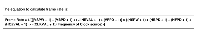
1 Frame_Rate = 1/[{(VSPW + 1) + (VBPD + 1) + (LIINEVAL + 1) + (VFPD + 1)} * {(HSPW + 1) + (    HBPD + 1) + (HFPD + 1) + (HOZVAL + 1)} * {(CLKVAL + 1)/(Frequency of Clock source)}]
2
3    50 = 1 / [{10 + 13 + 480 + 22} * {20 + 26 + 800 + 210} * X / 800M]
4    50 = 1 / [525 * 1056 * X / 800M]
5    1 = 50 * 525 * 1056 * X / 800M
6    800M = 50 * 525 * 1056 * X
7    X = 800M / (50 * 525 * 1056)
8    X = 800M / 27720000
9    X = 28.8
四:I2C裸板驱动驱动编写
4.1 I2C总线介绍
I2C总线有两条总线线路,一条是串行数据线(SDA),一条是串行时钟线(SCL)。SDA负责数据传输,SCL负责数据传输的时钟同步。I2C设备通过这两条总线连接到处理器的I2C总线控制器上。I2C总线最主要的特点就是其简单性、有效性以及支持多主控,其中任何能进行发送和接收的的设备都可以成为主控设备。主控设备能控制信号的传输和时钟平率,当然,在同一时间内只能有一个主控设备占用总线;
与其他总线相比,I2C总线有很多重要的特点:
主要特点:
(1)每一个连接到总线的设备都可以通过唯一的设备地址单独访问
(2)串行的8位双向数据传输,位速率在标准模式下可达到100kb/s;快速模式下可以达到400kb/s;告诉模式下可以达到3.4Mb/s
(3)总线长度最长7.6m左右
(4)片上滤波器可以增加抗干扰能力,保证数据的完成传输
(5)连接到一条I2C总线上的设备数量只受到最大电容400pF的限制
(6)它是一个多主机系统,在一条总线上可以同时有多个主机存在,通过冲突检测方式和延时等待防止数据不被破坏。同一时间只能有一个主机占用总线
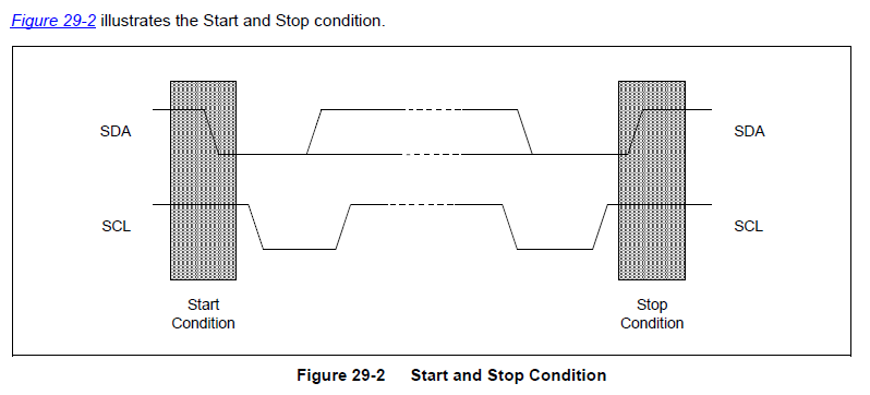
IIC总线在传输数据的过程中有3种类型的信号:开始信号、结束信号、和应答信号
开始信号(S): 当SCL为高电平时,SDA由高电平向低电平跳变,表示将要开始传输数据
结束信号(P):当SCL为高电平时,SDA由低电平向高电平跳变,表示结束传输数据
响应信号(ACK): 从机接收到8位数据后,在第9个周期,拉低SDA电平,表示已经收到数据。这个信号称为应答信号
如下图:
主机:IIC总线中发送命令的设备,对于ARM处理器来说,主机就是IIC控制器
从机:接受命令的设备
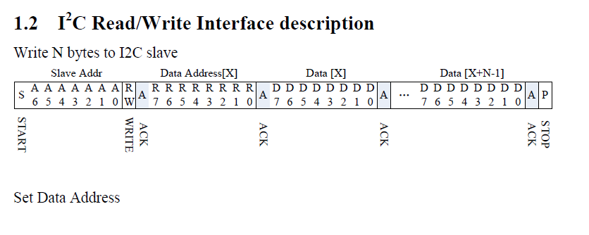
一个典型的I2C通信的数据帧格式如下图所示:
Write:在写入时,I2C主控设备先发起起始位(S),抢占总线,然后,发送7位设备地址和1位0,表示对设备的写入,接着就是向设备传送数据
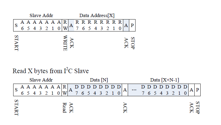
在读取时,稍微复杂点,因为总线的数据传输方向要改变,其流程总结如下:
(1)I2C主控设备发送起始位(S),抢占总线
(2)发送7位的设备地址和1位0,表示对设备的写入
(3)向设备写入要读取的寄存器地址
(4)再次发送起始位(S)
(5)发送7位设备地址和1位1,表示设备的读取
(6)从设备读取数据
无论要读取还是写入,都必须先写
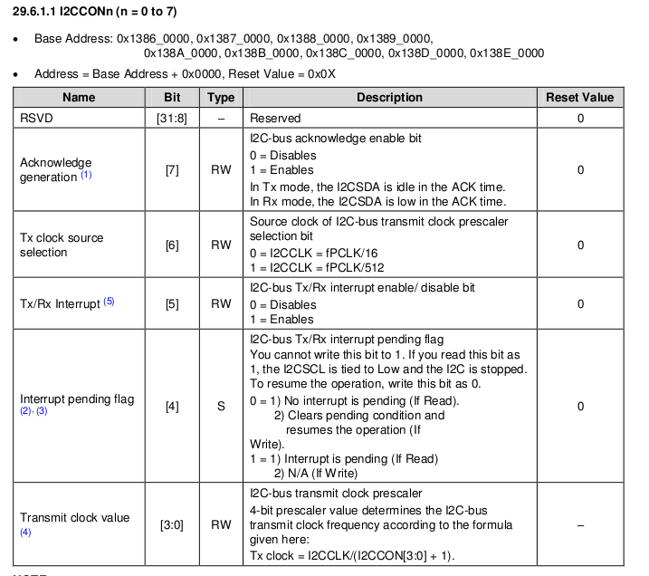
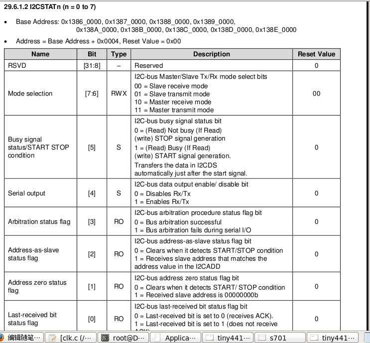
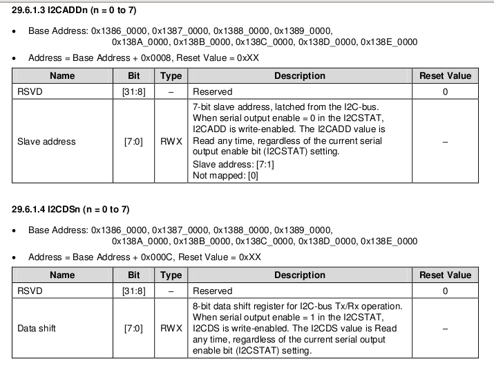
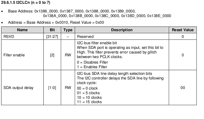
4.2 I2C总线寄存器介绍
I2C总线控制器的结构如下图:
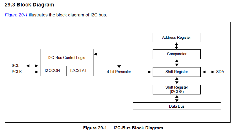
其中,PCLK是系统的外设时钟,SCL,SDA对应I2C总线的信号,控制器主要包括如下4个寄存器:
(1)I2CCON——I2C总线控制器,可以设置总线控制器的开启,关闭,中断以及总线的分频器;
(2)I2CSTAT——可控制总线的状态,包括发送、接收、主/ 从应答等状态;
(3)I2CADD——I2C总线地址寄存器,一个完整的的I2C总线控制器要求有4种工作模式:主设备发送,主设备接收,从设备发送,从设备接收;
(4)I2CDS——I2C数据接收、发送寄存器;
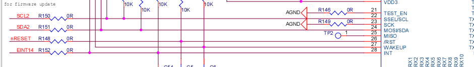
4.3 I2C总线gpio及寄存器的配置
从电电路图可知:lcd用到的是SDA2、SCL2
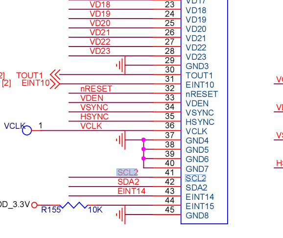
找到lcd接到底板的电路,查看SCL2对应的网标
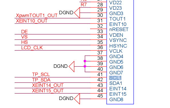
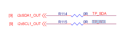
再找到底板连到核心板的网标,找到对应的gpio(gpd1_2 gpd1_3)

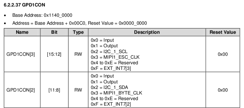
下面是I2C具体的寄存器配置
五:利用I2C读取触摸屏数据,控制lcd
由电路图可知,tiny4412开发板的触摸屏是由FT5206GE1这个芯片控制,触摸屏所产生的数据都放在该芯片的寄存器,因此我们只需要读它里面的值就可以了

由电路图我们还可以看出,触摸屏中断为EINT14,因此当我们触碰屏的时候就会发生中断,通过网标我们可以找到触摸屏的中断号:
通过datasheet我们可以找到触摸屏中断号为 62

对应的gpio为:gpx1_6
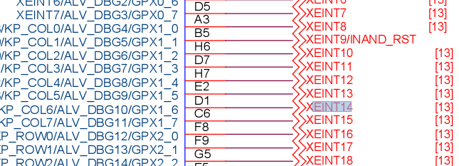
接下来找到对应的寄存器进行配置:
下面代码就是通过I2C读取触摸屏的数据,从而控制lcd进行显示:
#ifndef _LCD_H
#define _LCD_H
void (*udelay)(int ) = 0xc3e04fec;
void iic_master_read_buff(unsigned char slave_addr, char *data, int len);
void iic_init();
void iic_dest();
void ts_handle();
static int codate[5];

void iic_init();
void images_write_to_buff(unsigned int height, unsigned int width, char *, unsigned long addr);
void memcpy(unsigned char *dest, unsigned char *src, unsigned int len);
void init_table(unsigned long *addr);
void irq_init();
void enable_mmu();
void init_images();
void show_next();
void show_pre();
void do_irq();

extern unsigned long vector_start;
unsigned long space;
unsigned char *tmp;
unsigned char *fb;
#endif
#ifndef __REGS_H
#define __REGS_H

#define FRAMEBUFFER00 0x5f000000
#define ADDR0  0x5f000000
#define ADDR1  0x60000000
#define ADDR2  0x68000000

#define GPD1CON        (*(volatile unsigned long *)0x114000C0)
#define GPD1PUD         (*(volatile unsigned long *)0x114000C8)
#define I2CCON1         (*(volatile unsigned long *)0x13870000)
#define I2CADD1         (*(volatile unsigned long *)0x13870008)
#define I2CSTAT1        (*(volatile unsigned long *)0x13870004)
#define I2CDS1          (*(volatile unsigned long *)0x1387000C)
#define I2CLC1          (*(volatile unsigned long *)0x13870010)

#define ICCICR_CPU0        (*(volatile unsigned long *)0x10480000)
#define ICCPMR_CPU0        (*(volatile unsigned long *)0x10480004)
#define ICDDCR            (*(volatile unsigned long *)0x10490000)
#define ICDIPR15_CPU0    (*(volatile unsigned long *)0x1049043C)
#define ICDIPTR15_CPU0    (*(volatile unsigned long *)0x1049083C)
#define ICDISER1_CPU0    (*(volatile unsigned long *)0x10490104)
#define ICDSGIR            (*(volatile unsigned long *)0x10490f00)
#define ICCIAR_CPU0     (*(volatile unsigned long *)0x1048000C)
#define ICCEOIR_CPU0     (*(volatile unsigned long *)0x10480010)

#define GPX1CON            (*(volatile unsigned long *)0x11000C20)

#define EXT_INT41_CON        (*(volatile unsigned long *)0x11000E04)
#define EXT_INT41_MASK        (*(volatile unsigned long *)0x11000F04)
#define EXT_INT41_PEND        (*(volatile unsigned long *)0x11000F44)


#define printf(...) (((int (*)(const char *, ...))0xc3e114d8)(__VA_ARGS__))

#define GPX3CON (*(volatile unsigned long *)0x11000c60)
#define GPX3DAT    (*(volatile unsigned long *)0x11000c64)
#define GPD0CON    (*(volatile unsigned long *)0x110000a0)
#define GPD0DAT    (*(volatile unsigned long *)0x110000a4)

#define ICCICR_CPU0        (*(volatile unsigned long *)0x10480000)
#define ICCPMR_CPU0        (*(volatile unsigned long *)0x10480004)
#define ICDDCR            (*(volatile unsigned long *)0x10490000)
#define ICDIPR16_CPU0    (*(volatile unsigned long *)0x10490440)
#define ICDIPTR16_CPU0    (*(volatile unsigned long *)0x10490840)
#define ICDISER2_CPU0    (*(volatile unsigned long *)0x10490108)
#define ICDSGIR            (*(volatile unsigned long *)0x10490f00)
#define ICCIAR_CPU0     (*(volatile unsigned long *)0x1048000C)
#define ICCEOIR_CPU0     (*(volatile unsigned long *)0x10480010)

#define EXT_INT43_CON        (*(volatile unsigned long *)0x11000E0C)
#define EXT_INT43_MASK        (*(volatile unsigned long *)0x11000F0C)
#define EXT_INT43_PEND        (*(volatile unsigned long *)0x11000F4C)

#define CLK_DIV_LCD (*(volatile unsigned int *)0x1003c534)
#define CLK_SRC_MASK_LCD (*(volatile unsigned int *)0x1003c334)
#define CLK_GATE_IP_LCD (*(volatile unsigned int *)0x1003c934)
#define CLK_SRC_LCD0 (*(volatile unsigned int *)0x1003c234)

#define GPF0CON (*(volatile unsigned int *)0x11400180)
#define GPF1CON (*(volatile unsigned int *)0x114001a0)
#define GPF2CON (*(volatile unsigned int *)0x114001c0)
#define GPF3CON (*(volatile unsigned int *)0x114001e0)
#define GPF0DRV (*(volatile unsigned int *)0x1140018c)
#define GPF1DRV (*(volatile unsigned int *)0x114001ac)
#define GPF2DRV (*(volatile unsigned int *)0x114001cc)
#define GPF3DRV (*(volatile unsigned int *)0x114001ec)

#define LCDBLK_CFG (*(volatile unsigned int *)0x10010210)
#define LCDBLK_CFG2 (*(volatile unsigned int *)0x10010214)

#define LCD_BASE 0x11C00000

#define VIDCON0     (*(volatile unsigned int *)(LCD_BASE + 0x0000))
#define VIDCON1     (*(volatile unsigned int *)(LCD_BASE + 0x0004))
#define VIDCON2     (*(volatile unsigned int *)(LCD_BASE + 0x0008))
#define VIDCON3     (*(volatile unsigned int *)(LCD_BASE + 0x000C))
#define VIDTCON0     (*(volatile unsigned int *)(LCD_BASE + 0x0010))
#define VIDTCON1     (*(volatile unsigned int *)(LCD_BASE + 0x0014))
#define VIDTCON2     (*(volatile unsigned int *)(LCD_BASE + 0x0018))
#define VIDTCON3     (*(volatile unsigned int *)(LCD_BASE + 0x001C))
#define WINCON0     (*(volatile unsigned int *)(LCD_BASE + 0x0020))
#define WINCON1     (*(volatile unsigned int *)(LCD_BASE + 0x0024))
#define WINCON2     (*(volatile unsigned int *)(LCD_BASE + 0x0028))
#define WINCON3     (*(volatile unsigned int *)(LCD_BASE + 0x002C))
#define WINCON4     (*(volatile unsigned int *)(LCD_BASE + 0x0030))
#define SHADOWCON     (*(volatile unsigned int *)(LCD_BASE + 0x0034))
#define WINCHMAP2     (*(volatile unsigned int *)(LCD_BASE + 0x003C))
#define VIDOSD0A     (*(volatile unsigned int *)(LCD_BASE + 0x0040))
#define VIDOSD0B     (*(volatile unsigned int *)(LCD_BASE + 0x0044))
#define VIDOSD0C     (*(volatile unsigned int *)(LCD_BASE + 0x0048))
#define VIDOSD1A     (*(volatile unsigned int *)(LCD_BASE + 0x0050))
#define VIDOSD1B     (*(volatile unsigned int *)(LCD_BASE + 0x0054))
#define VIDOSD1C     (*(volatile unsigned int *)(LCD_BASE + 0x0058))
#define VIDOSD1D     (*(volatile unsigned int *)(LCD_BASE + 0x005C))
#define VIDOSD2A     (*(volatile unsigned int *)(LCD_BASE + 0x0060))
#define VIDOSD2B     (*(volatile unsigned int *)(LCD_BASE + 0x0064))
#define VIDOSD2C     (*(volatile unsigned int *)(LCD_BASE + 0x0068))
#define VIDOSD2D     (*(volatile unsigned int *)(LCD_BASE + 0x006C))
#define VIDOSD3A     (*(volatile unsigned int *)(LCD_BASE + 0x0070))
#define VIDOSD3B     (*(volatile unsigned int *)(LCD_BASE + 0x0074))
#define VIDOSD3C     (*(volatile unsigned int *)(LCD_BASE + 0x0078))
#define VIDOSD4A     (*(volatile unsigned int *)(LCD_BASE + 0x0080))
#define VIDOSD4B     (*(volatile unsigned int *)(LCD_BASE + 0x0084))
#define VIDOSD4C     (*(volatile unsigned int *)(LCD_BASE + 0x0088))
#define VIDW00ADD0B0     (*(volatile unsigned int *)(LCD_BASE + 0x00A0))
#define VIDW00ADD0B1     (*(volatile unsigned int *)(LCD_BASE + 0x00A4))
#define VIDW00ADD0B2     (*(volatile unsigned int *)(LCD_BASE + 0x20A0))
#define VIDW01ADD0B0     (*(volatile unsigned int *)(LCD_BASE + 0x00A8))
#define VIDW01ADD0B1     (*(volatile unsigned int *)(LCD_BASE + 0x00AC))
#define VIDW01ADD0B2     (*(volatile unsigned int *)(LCD_BASE + 0x20A8))
#define VIDW02ADD0B0     (*(volatile unsigned int *)(LCD_BASE + 0x00B0))
#define VIDW02ADD0B1     (*(volatile unsigned int *)(LCD_BASE + 0x00B4))
#define VIDW02ADD0B2     (*(volatile unsigned int *)(LCD_BASE + 0x20B0))
#define VIDW03ADD0B0     (*(volatile unsigned int *)(LCD_BASE + 0x00B8))
#define VIDW03ADD0B1     (*(volatile unsigned int *)(LCD_BASE + 0x00BC))
#define VIDW03ADD0B2     (*(volatile unsigned int *)(LCD_BASE + 0x20B8))
#define VIDW04ADD0B0     (*(volatile unsigned int *)(LCD_BASE + 0x00C0))
#define VIDW04ADD0B1     (*(volatile unsigned int *)(LCD_BASE + 0x00C4))
#define VIDW04ADD0B2     (*(volatile unsigned int *)(LCD_BASE + 0x20C0))
#define VIDW00ADD1B0     (*(volatile unsigned int *)(LCD_BASE + 0x00D0))
#define VIDW00ADD1B1     (*(volatile unsigned int *)(LCD_BASE + 0x00D4))
#define VIDW00ADD1B2     (*(volatile unsigned int *)(LCD_BASE + 0x20D0))
#define VIDW01ADD1B0     (*(volatile unsigned int *)(LCD_BASE + 0x00D8))
#define VIDW01ADD1B1     (*(volatile unsigned int *)(LCD_BASE + 0x00DC))
#define VIDW01ADD1B2     (*(volatile unsigned int *)(LCD_BASE + 0x20D8))
#define VIDW02ADD1B0     (*(volatile unsigned int *)(LCD_BASE + 0x00E0))
#define VIDW02ADD1B1     (*(volatile unsigned int *)(LCD_BASE + 0x00E4))
#define VIDW02ADD1B2     (*(volatile unsigned int *)(LCD_BASE + 0x20E0))
#define VIDW03ADD1B0     (*(volatile unsigned int *)(LCD_BASE + 0x00E8))
#define VIDW03ADD1B1     (*(volatile unsigned int *)(LCD_BASE + 0x00EC))
#define VIDW03ADD1B2     (*(volatile unsigned int *)(LCD_BASE + 0x20E8))
#define VIDW04ADD1B0     (*(volatile unsigned int *)(LCD_BASE + 0x00F0))
#define VIDW04ADD1B1     (*(volatile unsigned int *)(LCD_BASE + 0x00F4))
#define VIDW04ADD1B2     (*(volatile unsigned int *)(LCD_BASE + 0x20F0))
#define VIDW00ADD2     (*(volatile unsigned int *)(LCD_BASE + 0x0100))
#define VIDW01ADD2     (*(volatile unsigned int *)(LCD_BASE + 0x0104))
#define VIDW02ADD2     (*(volatile unsigned int *)(LCD_BASE + 0x0108))
#define VIDW03ADD2     (*(volatile unsigned int *)(LCD_BASE + 0x010C))
#define VIDW04ADD2     (*(volatile unsigned int *)(LCD_BASE + 0x0110))
#define VIDINTCON0     (*(volatile unsigned int *)(LCD_BASE + 0x0130))
#define VIDINTCON1     (*(volatile unsigned int *)(LCD_BASE + 0x0134))
#define W1KEYCON0     (*(volatile unsigned int *)(LCD_BASE + 0x0140))
#define VIDW0ALPHA0     (*(volatile unsigned int *)(LCD_BASE + 0x021C))
#define VIDW0ALPHA1     (*(volatile unsigned int *)(LCD_BASE + 0x0220))
#define VIDW1ALPHA0     (*(volatile unsigned int *)(LCD_BASE + 0x0224))
#define VIDW1ALPHA1     (*(volatile unsigned int *)(LCD_BASE + 0x0228))
#define VIDW2ALPHA0     (*(volatile unsigned int *)(LCD_BASE + 0x022C))
#define VIDW2ALPHA1     (*(volatile unsigned int *)(LCD_BASE + 0x0230))
#define VIDW3ALPHA0     (*(volatile unsigned int *)(LCD_BASE + 0x0234))
#define VIDW3ALPHA1     (*(volatile unsigned int *)(LCD_BASE + 0x0238))
#define VIDW4ALPHA0     (*(volatile unsigned int *)(LCD_BASE + 0x023C))
#define VIDW4ALPHA1     (*(volatile unsigned int *)(LCD_BASE + 0x0240))

#endif
  1 #include "lcd.h"
  2 #include "regs.h"
  3 #include "images.h"
  4
  5 int main(void)
  6 {
  7     *(unsigned long *)0x47000000 = do_irq;
  8   lcd_init();
  9     irq_init();
 10     init_images();
 11     enable_mmu();
 12     memcpy(0x0, vector_start, 0x1000);
 13 }
 14
 15 void images_write_to_buff(unsigned int height, unsigned int width, char *images, unsigned long addr )
 16 {
 17     int i, j;
 18     unsigned char *data;
 19     fb = addr;
 20     data = images;
 21     for(i = 0; i < height; i++) {
 22         for(j = 0; j < width; j++) {
 23             HEADER_PIXEL(data, (fb + (i * width + j) * 4)); //以每个像素点读去数据
 24         }
 25     }
 26
 27 }
 28
 29 /*将图片信息加载进来*/
 30 void init_images()
 31 {
 32     int i;
 33     char *head_data[10] = {header_data0, header_data1, header_data2, header_data3,
 34                     header_data4, header_data5, header_data6, header_data7,
 35                     header_data8, header_data9};
 36     space = 0x1000000;
 37     tmp = ADDR0;
 38
 39     for(i = 0; i < 10; i++) {
 40         images_write_to_buff(480, 800, head_data[i], tmp);
 41         tmp += space;
 42     }
 43
 44     tmp = ADDR0;
 45 }
 46
 47 void show_next()
 48 {
 49     if(tmp >= ADDR2) //判断是否到达最后一张图片
 50         tmp = ADDR0;
 51     else
 52         tmp += space;
 53
 54     VIDW00ADD0B0 = tmp; //framebuff start addr
 55     VIDW00ADD1B0 = tmp + VIDOSD0C * 4; //frambuff end addr
 56     VIDW00ADD2  = 800;
 57 }
 58
 59 void show_pre()
 60 {
 61     if(tmp <= ADDR1) //判断是否到达第一张图片
 62         tmp = ADDR2;
 63     else
 64         tmp -= space;
 65
 66     VIDW00ADD0B0 = tmp;
 67     VIDW00ADD1B0 = tmp + VIDOSD0C * 4;
 68     VIDW00ADD2  = 800;
 69 }
 70
 71 void do_irq()
 72 {
 73 #if 1
 74     unsigned long irq = 0;
 75
 76     if(EXT_INT41_PEND & (1 << 6))//if interrupt occur
 77     {
 78         EXT_INT41_PEND |= (1 << 6);//clean interrupt
 79
 80         ts_handle(); // handle interrupt func
 81         udelay(5000);
 82     }
 83 #else
 84     unsigned long data = ICCIAR_CPU0;
 85     unsigned int irq = data & 0x3ff;
 86     unsigned int cpu = (data >> 10) & 0x7;
 87     ICCEOIR_CPU0 = irq | (cpu << 10);
 88
 89     if(64 == irq) {
 90         if(EXT_INT43_PEND & (0x1 << 3)) {
 91             EXT_INT43_PEND |= (0x1 << 3);
 92             show_next();
 93             printf("next picture
");
 94         }
 95         if (EXT_INT43_PEND & (0x1 << 5)) {
 96             EXT_INT43_PEND |= (0x1 << 5);
 97             show_pre();
 98             printf("pre picture
");
 99         }
100
101     }
102 #endif
103 }
104
105 void iic_init()
106 {
107         GPD1CON &= ~(0xff << 8);//Xi2c1SDA/GPD1_2 ; Xi2c1SCL/GPD1_3
108      GPD1CON |= (0x22 << 8);//GPD1_2 --> 0x2 = I2C_1_SDA; GPD1_3 --> 0x2 = I2C_1_SCL
109      GPD1PUD = 0;//Disables Pull-up/Pull-down
110
111      I2CCON1 = 0x2 | (1 << 5) | (1 << 6);//100000000/512/3==65kb
112 //     I2CADD1 = 0xc0;//slave address
113      I2CSTAT1 = (1 << 4);//Enables Rx/Tx
114      I2CLC1 = 0x7;//0111 Enables Filter;15 clocks
115 }
116
117 void iic_dest()
118 {
119     I2CCON1 = 0;
120     I2CSTAT1 = 0;
121     I2CADD1 = 0;
122     I2CLC1 = 0;
123 }
124
125 void iic_master_read_buff(unsigned char slave_addr, char *data, int len)
126 {
127     iic_dest();
128     iic_init();
129
130     int cnt = 0;
131     while(I2CSTAT1 & (1))//if (write) START signal generation
132     {
133         I2CSTAT1 = 0X90;
134         udelay(100);
135         printf("i am I2CSTATZZ1 1
");
136     }
137
138     I2CCON1 |= (1 << 7);//I2C-bus acknowledge enable bit
139     I2CDS1 = slave_addr; //Slave address
140     I2CSTAT1 = 0Xb0;//1011 Master receive mode ;(Read) Busy (If Read; Enables Rx/Tx
141
142     while(I2CSTAT1 & 1)//(Read) Busy If Read
143     {
144         printf("i am I2CSTAT1 2
");
145     }
146     udelay(100);
147
148     char tmp = I2CDS1;//第一个数据,为传过去的地址
149     I2CCON1 &= ~(1 << 4);//No interrupt is pending (If Read). Clears pending condition and resumes the operation (If Write).
150     udelay(100);
151
152     while(cnt < len)
153     {
154         if((I2CCON1 & 0x10))
155         {
156             data[cnt] = I2CDS1; //read read a byte data of each
157             I2CCON1 &= ~(1 << 4); //No interrupt is pending (If Read). Clears pending condition and resumes the operation (If Write).
158             udelay(100);
159             cnt++;
160         }
161     }
162
163     I2CSTAT1 = 0X90;//1001 Master receive mode;(Read) Not busy (If Read); enables Rx/Tx; h
164 }
165
166 void ts_handle()
167 {
168     unsigned short x, y;
169     unsigned char buf[32];
170     static int m = 0;
171
172     iic_master_read_buff(0x70, buf, 31); //0x70为触摸屏地址
173     x = (buf[4] & 0x0f) << 8 | buf[5];
174
175     if(m < 5)
176         codate[m++] = x;
177
178     /*judge left or right of gesture*/
179     else {
180         if(codate[2] < codate[4]) { //right
181             printf("move right
");
182             show_next();
183         }
184
185         else if(codate[2] > codate[4]) { //left
186             printf("move left
");
187             show_pre();
188         }
189
190         /*clean codate */
191         for(m = 0; m < 5; m++) {
192             codate[m] = 0;
193         }
194         m = 0;
195         udelay(250000);
196     }
197 }
198
199 void irq_init()
200 {
201 #if 1
202     //step 1: enable cpu cpsr
203     __asm__ __volatile__(
204         "mrs r0, cpsr
"
205         "bic r0, r0, #0x80
"
206         "msr cpsr, r0
"
207         ::: "r0"
208     );
209
210     //step 2: GIC NO.62
211     ICCICR_CPU0 = 1;//global enable interrupt (total switch)
212     ICCPMR_CPU0 = 0xff;//This register provides an interrupt priority filter. Only interrupts with higher priority than the value in this registercan be signaled to the processor
213
214     ICDDCR = 1;//This register enables forwarding of pending interrupts to the CPU interfaces
215
216     /*一共有1024个中断源,只有160个中断号*/
217     //id = 62. 一个ICDIPR 控制4个中断,62 / 4 = 15 ...2, so ICDIPR=15
218     ICDIPR15_CPU0 = ~(0xff << 16);//the zero is the highest priority
219     ICDIPTR15_CPU0 = (1 << 16);//0x1 ---> for cpu0
220     ICDISER1_CPU0 = (1 << 30);// enable interrupt 0
221
222     //step 3: set gpio
223     GPX1CON &= ~(0xf << 24);
224     GPX1CON |= (0xf << 24);//xeint14 <==> gpx1_6 ---->0xF = EXT_INT41[6]
225
226     //step 4:set ext_int
227     EXT_INT41_CON &= ~(0x7 << 24);
228     EXT_INT41_CON |= (0x3 << 24);//falling edge; low level
229     EXT_INT41_MASK &= ~(0x1 << 6);//enable extint41_6
230
231 #else
232     //step 1: cpu permit interrupt
233      __asm__ __volatile__(
234              "mrs r0, cpsr
"
235              "bic r0,r0, #0x80
"
236              "msr cpsr, r0
"
237              :::"r0"
238      );
239
240      //step 2: GIC (cgi) enable
241      ICCICR_CPU0 = 1; //总开关
242      ICCPMR_CPU0 =0xff;//总优先级
243      ICDDCR = 1; //本中断开关
244
245      //KEY
246      ICDIPR16_CPU0 = (1 << 0);//本中断优先级
247      ICDIPTR16_CPU0 = (1 << 0);//目标cpu
248      ICDISER2_CPU0 = (1 << 0);//启用本中断
249
250     //step 3: Xeint
251          EXT_INT43_CON = (0x2 << 12);
252          EXT_INT43_CON = (0x2 << 20);
253          EXT_INT43_MASK = 0;
254
255     //step 4: set gpio
256     GPX3CON = (0xf << 8);
257     GPX3CON = (0xf << 20);
258
259     //step 5: interrupt source
260 #endif
261 }
262
263 void memcpy(unsigned char *dest, unsigned char *src, unsigned int len)
264 {
265     int i = 0;
266     for(i = 0; i < len; i++) {
267         dest[i] = src[i];
268     }
269 }
270
271 void init_table(unsigned long *addr)
272 {
273     unsigned long va = 0;
274         unsigned long phys = 0;
275
276         //0x40000000-0x80000000 -> 0x40000000-0x80000000
277         for(va = 0x40000000; va < 0x80000000; va += 0x100000) {
278                 phys = va;
279                 addr[va >> 20] = phys | 2;
280         }
281
282         //0x10000000-0x14000000 -> 0x10000000-0x140000000
283         for(va = 0x10000000; va < 0x14000000; va += 0x100000) {
284                 phys = va;
285                 addr[va >> 20] = phys | 2;
286         }
287         //0x10000000-0x14000000 -> 0x10000000-0x140000000
288         for(va = 0x0; va < 0x10000000; va += 0x100000) {
289                 phys = va + 0x70000000;
290                 addr[va >> 20] = phys | 2;
291         }
292
293 }
294
295 void enable_mmu()
296 {
297     /*构建表*/
298          unsigned long addr = 0x50000000;
299          init_table(addr);
300
301          /*打开mmu*/
302          unsigned long mmu = 0;
303          mmu = 1 | (1 << 1) | (1 << 3) | (1 << 8);
304          __asm__ __volatile__ (
305                  "mov r0, #3
"
306                  "MCR p15, 0, r0, c3, c0, 0
"//设置为管理员
307                  "MCR p15, 0, %0, c2, c0, 0
"//设置表的地址
308                  "MCR p15, 0, %1, c1, c0, 0
"//开启mmu
309                  :
310                  :       "r" (addr), "r" (mmu)
311                  :
312          );
313
314 }
315
316 void lcd_init(void)
317 {
318     /*
319      *<Exyons 4412 datasheet pg138 pg141 pg144 pg147> *
320      * GPF0CON : [31:0] : 0x2
321      * GPF1CON : [31:0] : 0x2
322      * GPF2CON : [31:0] : 0x2
323      * GPF3CON : [31:0] : 0x2
324      * */
325
326     //定义IO引脚功能为RGB接口
327     GPF0CON = 0x22222222;
328     GPF1CON = 0x22222222;
329     GPF2CON = 0x22222222;
330     GPF3CON &= ~(0xffff);
331     GPF3CON |= 0x2222;
332
333     //max driver strebgh----
334     GPF0DRV = 0xffffffff;
335     GPF1DRV = 0xffffffff;
336     GPF2DRV = 0xffffffff;
337     GPF3DRV &= ~0xff;
338     GPF3DRV |= 0xff;
339     /*
340      *<Exyons 4412 datasheet pg526>
341      *CLK_DIV_LCD:
342      *          [3:0]:FIMD0_RATIO   0
343      *              SCLK_FIMD0 = MOUTFIMD0/(FIMD0_RATIO + 1)
344      *                         = MOUTFIMD0/1 = 800MHz
345      *              MOUTFIMD0 == SCLKmpll_user_t == 800MHz      <Exyons 4412 datasheet pg453> LCD0_BLK
346      * */
347
348     CLK_DIV_LCD &= ~0xf;
349     /*
350      *<Exyons 4412 datasheet pg501>
351      *CLK_SRC_LCD0:
352      *          [3:0]:FIMD0_SEL 0110 ===> SCLKmpll_user_t 选择时钟源为SCLKmpll_user_t
353      *
354      * */
355     CLK_SRC_LCD0 &= ~0xf;
356     CLK_SRC_LCD0 |= 6;
357     //LCD0_SYS_PWR_REG == 7 Don't use
358
359
360     /*<Exyons 4412 datasheet pg1799>
361      *Using the display controller data, you can select one of the above data paths by setting LCDBLK_CFG Register
362      *(0x1001_0210). For more information, refer to the "System Others" manual.
363      *
364      *
365      * <Exyons 4412 datasheet pg880>
366      * LCDBLK_CFG:
367      *          [1] : FIMD of LBLK0 Bypass Selection    1 : FIMD Bypass   使用FIMD接口
368      *
369      * LCDBLK_CFG :
370      *          [0]:MIE0_DISPON     1 :  PWM outpupt enable
371      *
372      *
373      * */
374     LCDBLK_CFG |= 1 << 1; //set FIMD
375        LCDBLK_CFG2 |= 1;
376
377     /*
378      *<Exyons 4412 datasheet pg1869>
379      *VIDCON0:
380      *     [13:6]: CLKVAL_F     //设置lcd时钟分频系数
381      *
382      *  VCLK == 33.3Mhz         <S700-AT070TN92 pg14> DCLK  Frequency ===> Type : 33.3Mhz
383      *  VCLK = FIMD * SCLK/(CLKVAL+1)
384      *  VCLK =  800000000 / (CLKVAL + 1)
385      *  33300000 = 800000000 /(CLKVAL + 1)
386      *  CLKVAL + 1 = 24.02
387      *  CLKVAL = 23
388      * */
389
390     //设置接口类型及时钟分频 33.3MHZ (配置时钟分频系数)
391     VIDCON0 = (1 << 17) | (23 << 6) | 3; /*(1 << 17)非常重要 不配制会出现色差*/
392     //VIDCON0 = (23 << 6) | 3;
393     /*
394      *<Exyons 4412 datasheet pg1870 pg1848(时序)> <S700-AT070TN92 pg13(时序)>
395      *VIDTCON1:
396      *      [5]:IVSYNC  ===> 1 : Inverted(反转)
397      *      [6]:IHSYNC  ===> 1 : Inverted(反转)
398      *      [7]:IVCLK   ===> 1 : Fetches video data at VCLK rising edge (下降沿触发)
399      *      [10:9]:FIXVCLK  ====> 01 : VCLK running
400      * */
401     /*VIDCON1主要设置像表时钟信号一直存在,且高电平有效,
402     而IHSYNC=1,极性反转IVSYNC=1,极性反转,这是由于S07的时序图中VSYNC和
403     HSYNC都是低脉冲有效,而Exynos4412芯片手册时序图,VSYNC 和HSYNC都是高脉冲有效
404     ,所以需要反转*/
405     VIDCON1 = (1 << 9) | (1 << 7) | (1 << 5) | (1 << 6); //配置时序相关
406
407     /*
408      *<Exyons 4412 datasheet pg1874 pg1848(时序)> <S700-AT070TN92 pg13(时序)>
409      *VIDTCON0:
410      *       [23:16]:  VBPD + 1 <------> tvpw (1 - 20)  13
411      *       [15:8]: VFPD + 1 <------> tvfp 22
412      *       [7:0]: VSPW  + 1 <------> tvb - tvpw = 23 - 13 = 10
413      * */
414     /*VIDTCONx用来设置时序和长宽等参数,这里就主要设置VBPD(vertical back porch)、
415      VFBD(vertical fro    ntporch)、VSPW(vertical sync pulse width)、
416     HBPD(horizontal backporch)、 HFPD(horizontal sync pul    se width)等参数*/
417     VIDTCON0 = (10 << 16) | (21 << 8) | (12); //配置时序间隔时间 (VIDTCON0 VIDTCON1)
418
419      /*<Exyons 4412 datasheet pg1874 pg1848(时序)> <S700-AT070TN92 pg13(时序)>
420      *VIDTCON1:
421      *       [23:16]:  HBPD + 1 <------> thpw (1 - 40)  36
422      *       [15:8]:   HFPD + 1 <------> thfp 210
423      *       [7:0]:    HSPW  + 1 <------> thb - thpw = 46 - 36 = 10
424      */
425     VIDTCON1 = (35 << 16) | (209 << 8) | (9);
426
427     /*
428      *<Exyons 4412 datasheet pg1875>
429      *
430      *HOZVAL = (Horizontal display size) – 1 and LINEVAL = (Vertical display size) – 1.
431      * Horizontal(水平) display size : 800
432      *Vertical(垂直) display size : 480
433      * */
434     VIDTCON2 = (479 << 11) | 799;
435
436     //win0
437 //#ifdef BPP565
438     /*
439      *<Exyons 4412 datasheet pg1877>
440      *WINCON0:
441      *  [16]:Specifies Half-Word swap control bit.  1 = Enables swap
442      *  [5:2]: Selects Bits Per Pixel (BPP) mode for Window image : 0101 ===> 16BPP
443      *  [1]:Enables/disables video output   1 = Enables
444      *
445      * */
446 //    WINCON0 = (1 << 16) | (5 << 2) | 1;
447
448     /*
449      *<Exyons 4412 datasheet pg1895>
450      *VIDOSD0C:Specifies the Window Size (窗口尺寸 单位为word)
451      *
452      *
453      * */
454 //    VIDOSD0C = 480 * 800 >> 1;
455 //#else
456     /*
457      *<Exyons 4412 datasheet pg1877>
458      *WINCON0:
459      *  [5:2]: Selects Bits Per Pixel (BPP) mode for Window image : 1011 ===> 24BPP
460      *  [1]:Enables/disables video output   1 = Enables
461      *
462      * */
463     /*Exynos4412的LCD控制器有overlay功能,它支持5个window。
464     这里只使用window0,设置其代码RGB模式为24bit,(A888)且使能window0
465     */
466     WINCON0 = (1 << 22) | (1 << 15) | (11 << 2) | 1;//配置窗口0颜色数据格式,使能视频数据输出
467
468     /*
469      *<Exyons 4412 datasheet pg1895>
470      *VIDOSD0C:Specifies the Window Size (窗口尺寸 单位为word)
471      *
472      *
473      * */
474     VIDOSD0C = 480 * 800; //windows size
475 //#endif
476
477     //SHADOWCON &= ~(1 << 5); Don't use
478
479     /*
480      *<Exyons 4412 datasheet pg1891 pg1801>
481      *[0]: Enables Channel 0. 1 = Enables
482      * */
483     /*配置SHADOWCON和WINCHMAP2、选择使能DMA通道0,
484     由于我们使用的是Window0,所以需要使能DMA通道0
485     */
486         SHADOWCON |= 1; //选择相应通道
487
488
489     /*
490      *<Exyons 4412 datasheet  pg1894 pg1801>
491      *[18:16] Selects Channel 0's channel. ===> 001 = Window 0
492      *[2:0] Selects Window 0's channel.  ===> 001 = Channel 0
493      *
494      *
495      * */
496     WINCHMAP2 &= ~(7 << 16);//选择通道与窗口
497     WINCHMAP2 |= 1 << 16;
498     WINCHMAP2 &= ~7;
499     WINCHMAP2 |= 1;
500
501     /*
502      *<Exyons 4412 datasheet  pg1895>
503      *VIDOSD0A: LCD左上角坐标
504      *VIDOSD0B: LCD右下角坐标
505      */
506
507     VIDOSD0A = 0;
508     VIDOSD0B = (799 << 11) | 479;
509
510     /*
511      *<Exyons 4412 datasheet  pg1902>
512      * VIDW00ADD0B0 : window0 frame buffer 起始地址
513      *  VIDW00ADD1B0 : window0 frame buffer 结束地址
514      * */
515     VIDW00ADD0B0 = FRAMEBUFFER00;
516     VIDW00ADD1B0 = FRAMEBUFFER00 + VIDOSD0C * 4;
517     VIDW00ADD2  = 800;
518     /*
519      * <Exyons 4412 datasheet pg1869>
520      * Display On: ENVID and ENVID_F are set to "1".
521      *  [0]:ENVID ===> 1 = Enables
522      *  [1]:ENVID_F ===> 1 = Enables
523      * */
524 }
525
526  __asm__(
527
528 /*异常向量表*/
529  "vector:
"
530  "       b reset
"
531  "       b und
"
532  "       b swi
"
533  "       b pre_abt
"
534  "       b data_abt
"
535  "       .word 0x0
"
536  "       b irq
"
537  "       b fiq
"
538  "reset:
"
539  "und:
"
540  "       mov sp, #0x47000000
"
541  "       stmdb sp!, {r0-r12, lr}
"
542
543  "       ldr r3, =0x47000004
"
544  "       ldr r2, [r3]
"
545  "       blx r2
"
546
547  "       mov sp, #0x47000000
"
548  "       ldmdb sp, {r0-r12, pc}^
"
549
550  "swi:
"
551  "       mov sp, #0x47000000
"
552  "       stmdb sp!, {r0-r12, lr}^
"
553
554  "       mov sp, #0x47000000
"
555  "       ldmdb sp, {r0-r12, pc}^
"
556
557  "pre_abt:
"
558
559  "data_abt:
"
560  "       mov sp, #0x47000000
"
561  "       sub lr, lr, #4
"
562  "       stmdb sp!, {r0-r12, lr}
"
563
564  "       ldr r3, =0x47000008
"
565  "       ldr r2, [r3]
"
566  "       blx r2
"
567
568  "       mov sp, #0x47000000
"
569  "       ldmdb sp, {r0-r12, pc}^
"
570  "irq:
"
571
572  "       mov sp, #0x47000000
"
573  "       sub lr, lr, #4
"
574  "       stmdb sp!, {r0-r12, lr}
"
575
576  "       ldr r3, =0x47000000
" //跳转到c语言
577  "       ldr r2, [r3]
"
578  "       blx r2
"
579
580  "       mov sp, #0x47000000
"
581  "       ldmdb sp, {r0-r12, pc}^
"
582
583  "fiq:
"
584
585          ".global vector_start
"
586  "vector_start:
"
587          ".word vector
 "
588
589  );