在3D图形计算中,deferred shading是一个基于屏幕空间的着色技术。之所以被称为deferred shading,是因为我们将场景的光照计算与渲染"deferred"到第二个pass。在第一个pass中,我们会将所有需要的数据(例如diffuse,normals,materials)渲染到一系列render targets中,这些render targets通常被称为geometry buffer(G-Buffer)。然后,在第二个pass中,从这些render targets中取出数据来执行光照计算与渲染。
Deferred shading技术的主要优点是它分离了场景中的光源与几何体。在我们熟悉的forward rendering技术中,为了渲染一盏光源的效果,我们不得不将在这盏光源范围内的几何体数据提交给GPU来进行计算与渲染。这个过程包含了许多states和shaders的切换,并且会产生大量的draw calls。而在deferred shading技术中,我们可以将许多光源甚至所有光源的计算与渲染在一个draw call中完成。所以当场景中的光源数量急剧增加时,deferred shading的优势将有巨大的体现。
Deferred shading技术的缺点在于它需要消耗更多的内存,带宽以及着色器指令。
下面通过一个例子来说明deferred shading的工作流程,在这个例子中,我在场景中发射了1024个粒子,每个粒子都被当作是一个点光源,最终效果如图:

首先来看下粒子的生成过程,我没有使用CPU来计算和生成粒子,而全部都是在GPU上完成的。我创建了四张32*32大小的纹理,纹理中的每个像素都代表了一个粒子,格式都是DXGI_FORMAT_R32G32B32A32_FLOAT。其中两张用于存储粒子的位置和生命周期,另外两张用于存储粒子的方向。这里各创建两张的原因是需要做ping-ponging,因为同一张纹理是不能同时读取和写入的(在渲染时,我们将其中两张作为输入,另外两张作为输出。在下一帧,将它们互换)。
存储粒子位置和生命周期的纹理如图(随意截取了一帧的数据),其中x, y, z存储粒子的位置,而w存储粒子的生命周期: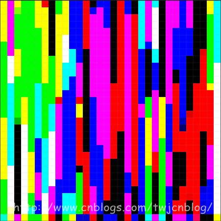
存储粒子方向的纹理如图(随意截取了一帧的数据),其中x, y, z存储粒子的方向,w没有使用:
每一帧,我都会根据上一帧粒子的位置和方向来计算出这一帧粒子的位置和方向:
PSOut main( PSIn pIn )
{
    PSOut psOut;

    int3 texCoord = int3( int2(pIn.position.xy), 0 );

    // 采样上一帧粒子的位置和方向
    float4 position = texPositions.Load( texCoord );
    float4 direction = texDirections.Load( texCoord );

    // Tick
    position.w += frameTime;
    if ( position.w >= 4.0f )    // 粒子的生命周期是4秒
    {
        // 重置粒子
        direction.xyz = sprinkleDir;
        position.xyz = float3( 0.0f, -235.0f, 0.0f );
        position.w -= 4.0f;
    }
    else
    {
        // 计算重力
        direction.y -= (500.0f * frameTime);

        // 更新位置
        position.xyz += (direction.xyz * frameTime);

        // 伪物理,不让粒子超出场景的边界
        direction.xyz = ((position.xyz >  sceneBound) ? -0.8f * abs(direction.xyz) : direction.xyz);
        direction.xyz = ((position.xyz < -sceneBound) ?  0.8f * abs(direction.xyz) : direction.xyz);
        position.xyz = clamp( position.xyz, -sceneBound, sceneBound );
    }

    //
    psOut.position = position;
    psOut.direction = direction;

    //
    return psOut;
}
接着,在渲染粒子时,直接从计算完毕的纹理中采样粒子的位置数据,利用geometry shader生成朝向摄像机的面片,就完成了粒子的渲染:
[Geometry shader]

Texture1D texColors;
SamplerState samColors;

float4x4 viewProjMatrix;
float3 dirX, dirY;

[maxvertexcount(4)]
void main( point GSIn gIn[1], inout TriangleStream<PSIn> triStream )
{
    PSIn gsOut;

    //
    gsOut.color = texColors.SampleLevel(samColors, gIn[0].position.w * 0.25f, 0).rgb;

    // 输出朝向摄像机的面片
    gsOut.position = mul( viewProjMatrix, float4(gIn[0].position.xyz - dirX - dirY, 1.0f) );
    gsOut.texCoord = float2( 0.0f, 1.0f );
    triStream.Append( gsOut );

    gsOut.position = mul( viewProjMatrix, float4(gIn[0].position.xyz - dirX + dirY, 1.0f) );
    gsOut.texCoord = float2( 0.0f, 0.0f );
    triStream.Append( gsOut );

    gsOut.position = mul( viewProjMatrix, float4(gIn[0].position.xyz + dirX - dirY, 1.0f) );
    gsOut.texCoord = float2( 1.0f, 1.0f );
    triStream.Append( gsOut );

    gsOut.position = mul( viewProjMatrix, float4(gIn[0].position.xyz + dirX + dirY, 1.0f) );
    gsOut.texCoord = float2( 1.0f, 0.0f );
    triStream.Append( gsOut );
}

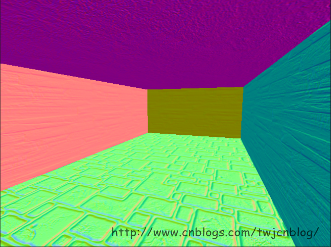
在计算完粒子的位置数据后,接着我们就渲染场景,在这个pass中,我们不计算光照,而仅仅是将场景的diffuse以及normal渲染到两张render targets中:
[Fragment shader]

struct PSOut
{
    float3 base        : SV_TARGET0;
    float3 normal    : SV_TARGET1;
};

Texture2D texDiffuse;
Texture2D texBumpMap;
SamplerState samTrilinearAnisoWrap;

PSOut main( PSIn pIn )
{
    float3 base = texDiffuse.Sample(samTrilinearAnisoWrap, pIn.texCoord).rgb;

    float3 bump = texBumpMap.Sample(samTrilinearAnisoWrap, pIn.texCoord).xyz;
    bump = 2.0f * bump - 1.0f;    // Convert from [0, 1] to [-1, 1]

    // 计算法线
    float3 normal = pIn.tangent * bump.x + pIn.binormal * bump.y + pIn.normal * bump.z;
    normal = normalize( normal );

    //
    PSOut psOut;
    psOut.base = base;
    psOut.normal = normal * 0.5f + 0.5f;    // Convert from [-1, 1] to [0, 1]

    return psOut;
}
这样,我们就有了用于在第二个pass中计算光照的G-Buffer数据:

至此,我们可以开始我们的deferred shading了。具体流程是这样的:每个粒子我们都把它作为一个点光源,一种简单的方法是针对每个粒子,我们都绘制一个全屏四边形,触发屏幕上每个像素的着色器,然后去计算光照,但是这种方法的效率太低了。所以我采用的方法是计算每个点光源的覆盖范围,然后生成一个表示覆盖范围的四边形,来触发在范围内的像素的着色器。计算覆盖范围的方法为,将粒子的位置转换到视图空间,然后根据设置的点光源的范围来生成四边形的四个顶点,再将这四个顶点转换到clip-space:
// 投影矩阵分量:
// projMatrix[0][0]
// projMatrix[1][1]
// projMatrix[2][2]
// projMatrix[3][2]
float4 projMatrixComponoents;

bool getScreenBox(
        const float3 pos,
        const float radius,
        out float xProjLeft, out float xProjRight,
        out float yProjTop, out float yProjBottom,
        out float zProjNear, out float zProjFar )
{
    // 初始化
    xProjLeft = -1;
    xProjRight = 1;
    yProjTop = 1;
    yProjBottom = -1;
    zProjNear = 0;
    zProjFar = 1;

    //
    float4 viewLightPosition = mul( viewMatrix, float4(pos, 1.0f) );

    // 计算z
    float zViewFar = viewLightPosition.z + radius;
    if ( zViewFar <= 0.0f )
    {
        // 光源完全位于摄像机之后
        return false;
    }

    //
    float zViewNear = max( viewLightPosition.z - radius, 0.00001f );

    //
    zProjNear = projMatrixComponoents.z + projMatrixComponoents.w / zViewNear;
    zProjFar = projMatrixComponoents.z + projMatrixComponoents.w / zViewFar;

    //
    // 计算clip-space的四边形
    //
    float xViewLeft = viewLightPosition.x - radius;
    xProjLeft = projMatrixComponoents.x * xViewLeft / viewLightPosition.z;
    if ( xProjLeft >= 1.0f )
    {
        // 光源完全位于投影范围的右边
        return false;
    }

    float xViewRight = viewLightPosition.x + radius;
    xProjRight = projMatrixComponoents.x * xViewRight / viewLightPosition.z;
    if ( xProjRight <= -1.0f )
    {
        // 光源完全位于投影范围的左边
        return false;
    }

    float yViewTop = viewLightPosition.y + radius;
    yProjTop = projMatrixComponoents.y * yViewTop / viewLightPosition.z;
    if ( yProjTop <= -1.0f )
    {
        // 光源完全位于投影范围的底部
        return false;
    }

    float yViewBottom = viewLightPosition.y - radius;
    yProjBottom = projMatrixComponoents.y * yViewBottom / viewLightPosition.z;
    if ( yProjBottom >= 1.0f )
    {
        // 光源完全位于投影范围的顶部
        return false;
    }

    // Clamp all
    xProjLeft = clamp( xProjLeft, -1.0f, xProjLeft );
    xProjRight = clamp( xProjRight, xProjRight, 1.0f );
    yProjTop = clamp( yProjTop, yProjTop, 1.0f );
    yProjBottom = clamp( yProjBottom, -1.0f, yProjBottom );

    return true;
}

接着,在光源范围内的像素的着色器被触发,我们就可以开始计算它们的光照了,从G-Buffer中采样diffuse和normal数据,进行常规的点光源光照计算即可:
[Fragment shader]

Texture2D texBaseGBuffer;
Texture2D texNormalGBuffer;
Texture2D texDepth;
SamplerState samPointClamp;

float4x4 invViewProjMatrix;

float3 main( PSIn pIn ) : SV_TARGET0
{
    float depth = texDepth.Sample(samPointClamp, pIn.texCoord).x;

    // 只计算在深度范围内的像素的光照
    [branch]
    if ( (depth >= pIn.zBounds.x) && (depth <= pIn.zBounds.y) )
    {
        float3 base = texBaseGBuffer.Sample(samPointClamp, pIn.texCoord).rgb;
        float3 normal = texNormalGBuffer.Sample(samPointClamp, pIn.texCoord).xyz * 2.0f - 1.0f;

        // Clip-space position,x和y的偏移量已经计算在invViewProjMatrix中,所以这里就不需要转换了
        float4 clipPosition = float4( pIn.texCoord, depth, 1.0f );

        // World-space position
        float4 worldPosition = mul( invViewProjMatrix, clipPosition );
        worldPosition.xyz /= worldPosition.w;

        // Lighting
        float3 lightDir = (pIn.lightPosition - worldPosition.xyz) / LIGHT_SIZE;

        //
        float atten = saturate( 1.0f - dot(lightDir, lightDir) );

        //
        lightDir = normalize( lightDir );
        float diffuse = saturate( dot(lightDir, normal) );

        return (0.7f * atten * pIn.color * (diffuse * base));
    }

    return 0;
}
至此,我们的deferred shading就完成了 o(∩_∩)o
