RTC
- 原创,转载请写明出处。
一直以来想写一篇关于RTC的总结,可是人太懒,在读完John Z. Sonmez大伽的《软技能代码之外的生存技能》后,终于下定决心,完成这项早已计划中的任务。首先声明,本文是以PC为例来阐述RTC工作的基本原理。
RTC的基本概念
RTC(Real Time Clock),实时时钟,是存在于PC(x86)及类PC架构的电路中,其主要的作用是记录设备关机时的时间及在设备开机时提供时间基准,也就是说在设备机器关电的时候,记录下当时的时间,在设备启动时为设备内部的时间提供基准值,从而使得设备内部的时间值不是从初值开始,而是从RTC记录并运行的时间开始。从这个意义上RTC有被成为墙上时间(walltimer)。
RTC电路
聪明的你,先来看下RTC电路
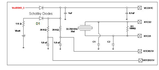
其中RTCX1,RTCX2, RTCRST#, SRTCRST#连接到PCH上, 所以上RTC的input和output都是受PCH的控制的,也就是说RTC提供的时间是给PCH的。
RTCX1为晶振的input,RTCX2为晶振的output,也就是晶振反馈值。
RTCRST#的主要作用是用来清楚CMOS的,当然它也可以用来检测电池的电压是否低于2V。
SRTCRST#用来当电池更换时清除Intel ME相关的寄存器。
Vbatt时由安装的一颗3V左右(一般为2.8V~3.3V)的纽扣电池(一般都为CR2302,提供最大10mA的电流)提供,这颗电池的作用时在机器移除AC电源后, RTC电路仍然可以正常工作。当这颗电池的电压不足的时候,就会出现RTC时间不准确。
Xtal是由一颗频率为32 .768KHz的石英晶振提供的, 此晶振的功能是提供给计时电路用的基准clock。
肖特基二极管D1的作用:当AC电源连接时,也就是VCCRTC(3.3V)有电时,D1不导通,电池不提供电流给RTC电路;当AC电源移除后,D1导通,电池工作。
RTC工作原理
提起RTC,不得不提起PC系统的另外一个时间,系统时间。在Linux和Windows中,这个时间都是内核在维护的,也就是说在Linux等操作系统中,有两套时间在运行。
系统时间的精度可以做到微妙级,而相对应的RTC的时间精度只能做到秒级。一般情况下系统时间的精度为24小时最大漂移1.2秒,RTC的时间的漂移就要大的多。这就造成了系统时间的精确的要远远高于RTC。所以当系统运行了一段时间后,会出现系统时间和RTC不一致的情况,这是就需要我们定期将两个时间进行同步。
RTC和CMOS
RTC的时间和设置都保存在CMOS RAM中,详细的如下表,其中前10个字节(offset 00 ~ 09h)存储着RTC确切的时间,也就是你在BIOS setup utility中看到的时间,当然这个时间是变动的,剩下的都是RTC的配置字节。可以通过70/71h端口去操作,也可以通过ioctl命令去配置。
|
Offset Hex |
Offset Dec |
Field Size |
Function |
|
00h |
0 |
1 byte |
RTC seconds. Contains the seconds value of current time |
|
01h |
1 |
1 byte |
RTC seconds alarm. Contains the seconds value for the RTC alarm |
|
02h |
2 |
1 byte |
RTC minutes. Contains the minutes value of the current time |
|
03h |
3 |
1 byte |
RTC minutes alarm. Contains the minutes value for the RTC alarm |
|
04h |
4 |
1 byte |
RTC hours. Contains the hours value of the current time |
|
05h |
5 |
1 byte |
RTC hours alarm. Contains the hours value for the RTC alarm |
|
06h |
6 |
1 byte |
RTC day of week. Contains the current day of the week |
|
07h |
7 |
1 byte |
RTC date day. Contains day value of current date |
|
08h |
8 |
1 byte |
RTC date month. Contains the month value of current date |
|
09h |
9 |
1 byte |
RTC date year. Contains the year value of current date |
|
0Ah |
10 |
1 byte |
Status Register A |
|
|
|
|
Bit 7 = Update in progress (0 = Date and time can be read, 1 = Time update in progress) |
|
|
|
|
Bits 6-4 = Time frequency divider (010 = 32.768KHz |
|
|
|
|
Bits 3-0 = Rate selection frequency (0110 = 1.024KHz square wave frequency) |
|
0Bh |
11 |
1 byte |
Status Register B |
|
|
|
|
Bit 7 = Clock update cycle (0 = Update normally, 1 = Abort update in progress) |
|
|
|
|
Bit 6 = Periodic interrupt (0 = Disable interrupt (default), 1 = Enable interrupt) |
|
|
|
|
Bit 5 = Alarm interrupt (0 = Disable interrupt (default), 1 = Enable interrupt) |
|
|
|
|
Bit 4 = Update ended interrupt (0 = Disable interrupt (default), 1 = Enable interrupt) |
|
|
|
|
Bit 3 = Status register A square wave frequency (0 = Disable square wave (default), 1 = Enable square wave) |
|
|
|
|
Bit 2 = 24 hour clock (0 = 24 hour mode (default), 1 = 12 hour mode) |
|
|
|
|
Bit 1 = Daylight savings time (0 = Disable daylight savings (default), 1 = Enable daylight savings) |
|
0Ch |
12 |
1 byte |
Status Register C - Read only flags indicating system status conditions |
|
|
|
|
Bit 7 = IRQF flag |
|
|
|
|
Bit 6 = PF flag |
|
|
|
|
Bit 5 = AF flag |
|
|
|
|
Bit 4 UF flag |
|
|
|
|
Bits 3-0 = Reserved |
|
0Dh |
13 |
1 byte |
Status Register D - Valid CMOS RAM flag on bit 7 (battery condition flag) |
|
|
|
|
Bit 7 = Valid CMOS RAM flag (0 = CMOS battery dead, 1 = CMOS battery power good) |
|
|
|
|
Bit 6-0 = Reserved |
|
0Eh |
14 |
1 byte |
Diagnostic Status |
|
|
|
|
Bit 7 = Real time clock power status (0 = CMOS has not lost power, 1 = CMOS has lost power) |
|
|
|
|
Bit 6 = CMOS checksum status (0 = Checksum is good, 1 = Checksum is bad) |
|
|
|
|
Bit 5 = POST configuration information status (0 = Configuration information is valid, 1 = Configuration information in invalid) |
|
|
|
|
Bit 4 = Memory size compare during POST (0 = POST memory equals configuration, 1 = POST memory not equal to configuration) |
|
|
|
|
Bit 3 = Fixed disk/adapter initialization (0 = Initialization good, 1 = Initialization bad) |
|
|
|
|
Bit 2 = CMOS time status indicator (0 = Time is valid, 1 = Time is invalid) |
|
|
|
|
Bit 1-0 = Reserved |
Linux下RTC相关函数
如果你通过70/71h端口去访问RTC的数据,在linux下有两种方式,第一种是通过函数inb级outb去操作,读取的
#include <sys/io.h>
iopl(3);
unsigned char index, data;
outb(index, 0x70);
data = inb(0x71);
第二种方式是通过访问/dev/port。
unsigned char index, data;
int fp = open("/dev/port",O_RDWR);
if(fp >0)
{
lseek(fp, 0x70, SEEK_SET);
write(fp, &index, 1);
lseek(fp, 0x71, SEEK_SET);
read(fp, data, 1);
}
close(fp);
以上都是以读取为例的,你可以将每一中方式最后一行的inb改为outb, read改为write就将读取改为设置了。
以上两种方式是常见的方式,实际上linux提供以一系列的ioctl命令去操作RTC的读取及配置。强烈推荐这种方式。
X86 架构的Linux下存在/dev/rtc这个字符型设备文件,有些有多个rtc设备的系统,可能会有/dev/rtc0…. /dev/rtc1等等。
首先需要打开rtc设备文件
#include <linux/rtc.h>
struct rtc_time rtc;
int fd = open("/dev/rtc", O_RDONLY);
if(fd <= 0)
{
fd = open("/dev/rtc0", O_RDONLY);
}
然后运行ioctl命令,
ret = ioctl(fd,RTC_RD_TIME, &rtc);
详细的rtc的ioctl命令可以参考linux/rtc.h文件
/*
* Generic RTC interface.
* This version contains the part of the user interface to the Real Time Clock
* service. It is used with both the legacy mc146818 and also EFI
* Struct rtc_time and first 12 ioctl by Paul Gortmaker, 1996 - separated out
* from <linux/mc146818rtc.h> to this file for 2.4 kernels.
*
* Copyright (C) 1999 Hewlett-Packard Co.
* Copyright (C) 1999 Stephane Eranian <eranian@hpl.hp.com>
*/
#ifndef _LINUX_RTC_H_
#define _LINUX_RTC_H_
/*
* The struct used to pass data via the following ioctl. Similar to the
* struct tm in <time.h>, but it needs to be here so that the kernel
* source is self contained, allowing cross-compiles, etc. etc.
*/
struct rtc_time {
int tm_sec;
int tm_min;
int tm_hour;
int tm_mday;
int tm_mon;
int tm_year;
int tm_wday;
int tm_yday;
int tm_isdst;
};
/*
* This data structure is inspired by the EFI (v0.92) wakeup
* alarm API.
*/
struct rtc_wkalrm {
unsigned char enabled; /* 0 = alarm disabled, 1 = alarm enabled */
unsigned char pending; /* 0 = alarm not pending, 1 = alarm pending */
struct rtc_time time; /* time the alarm is set to */
};
/*
* Data structure to control PLL correction some better RTC feature
* pll_value is used to get or set current value of correction,
* the rest of the struct is used to query HW capabilities.
* This is modeled after the RTC used in Q40/Q60 computers but
* should be sufficiently flexible for other devices
*
* +ve pll_value means clock will run faster by
* pll_value*pll_posmult/pll_clock
* -ve pll_value means clock will run slower by
* pll_value*pll_negmult/pll_clock
*/
struct rtc_pll_info {
int pll_ctrl; /* placeholder for fancier control */
int pll_value; /* get/set correction value */
int pll_max; /* max +ve (faster) adjustment value */
int pll_min; /* max -ve (slower) adjustment value */
int pll_posmult; /* factor for +ve correction */
int pll_negmult; /* factor for -ve correction */
long pll_clock; /* base PLL frequency */
};
/*
* ioctl calls that are permitted to the /dev/rtc interface, if
* any of the RTC drivers are enabled.
*/
#define RTC_AIE_ON _IO('p', 0x01) /* Alarm int. enable on */
#define RTC_AIE_OFF _IO('p', 0x02) /* ... off */
#define RTC_UIE_ON _IO('p', 0x03) /* Update int. enable on */
#define RTC_UIE_OFF _IO('p', 0x04) /* ... off */
#define RTC_PIE_ON _IO('p', 0x05) /* Periodic int. enable on */
#define RTC_PIE_OFF _IO('p', 0x06) /* ... off */
#define RTC_WIE_ON _IO('p', 0x0f) /* Watchdog int. enable on */
#define RTC_WIE_OFF _IO('p', 0x10) /* ... off */
#define RTC_ALM_SET _IOW('p', 0x07, struct rtc_time) /* Set alarm time */
#define RTC_ALM_READ _IOR('p', 0x08, struct rtc_time) /* Read alarm time */
#define RTC_RD_TIME _IOR('p', 0x09, struct rtc_time) /* Read RTC time */
#define RTC_SET_TIME _IOW('p', 0x0a, struct rtc_time) /* Set RTC time */
#define RTC_IRQP_READ _IOR('p', 0x0b, unsigned long) /* Read IRQ rate */
#define RTC_IRQP_SET _IOW('p', 0x0c, unsigned long) /* Set IRQ rate */
#define RTC_EPOCH_READ _IOR('p', 0x0d, unsigned long) /* Read epoch */
#define RTC_EPOCH_SET _IOW('p', 0x0e, unsigned long) /* Set epoch */
#define RTC_WKALM_SET _IOW('p', 0x0f, struct rtc_wkalrm)/* Set wakeup alarm*/
#define RTC_WKALM_RD _IOR('p', 0x10, struct rtc_wkalrm)/* Get wakeup alarm*/
#define RTC_PLL_GET _IOR('p', 0x11, struct rtc_pll_info) /* Get PLL correction */
#define RTC_PLL_SET _IOW('p', 0x12, struct rtc_pll_info) /* Set PLL correction */
/* interrupt flags */
#define RTC_IRQF 0x80 /* any of the following is active */
常用的是RTC_RD_TIME和RTC_SET_TIME, RTC_AIE_OFF, RTC_UIE_OFF,RTC_PIE_OFF尽量少用,或者说在没有搞懂原理之前,不要使用(RTC_AIE_ON可能会导致机器被唤醒),因为此3项配置可能会带来机器一些异常动作。
Linux RTC驱动
RTC的驱动代码在kernel代码的drivers/rtc目录下。在此目录下会看到一大堆文件,这是因为linux支持众多rtc设备,本文是以x86架构的rtc为例的。
RTC涉及的代码如下:
driver/rtc/class.c: 此文件向linux内核驱动模型注册了一个类RTC, 同时为底层的RTC驱动提供了注册/注销RTC接口。
driver/rtc/rtc-dev.c: 将各种各样的RTC设备抽象成一个字符设备,同时提供文件操作函数集。
driver/rtc/rtc-sysfs.c: 用户可以通过sysfs文件系统方便快捷的操作rtc设备。
driver/rtc/rtc-proc.c: 可以通过proc文件系统获得rtc的相关信息,比如rtc_time, rtc_data等信息。
driver/rtc/interface.c: 提供应用程序和驱动的接口函数,主要是为rtc提供相关的调用接口。
driver/rtc/rtc-lib.c: 提供了一个rtc和data以及time之间的转换函数
driver/rtc/hctosys.c: 用于开机启动的时候获取rtc的值。
driver/rtc/rtc-cmos.c: x86架构rtc驱动。
include/linux/rtc.h:定义了与RTC有关的数据结构
rtc-mc146818-lib.c
此文件中的函数的主要操作就是通过70h/71h, 72h/73h端口去读写cmos RAM去实现的,提供了最底层的和硬件交互的函数。
unsigned int mc146818_get_time(struct rtc_time *time): 获取rtc的时间。
int mc146818_set_time(struct rtc_time *time):设置rtc的 时间。
static inline unsigned char mc146818_is_updating(void):判断cmos的时间是否在更新中,如果是,delay后再设置。
rtc-cmos.c
此文件主要是一些操作CMOS RAM的函数,这些函数是rtc-mc146818-lib.c文件函数的上层,实际的实现在rtc-mc146818-lib.c中。
static const struct rtc_class_ops cmos_rtc_ops = {
.read_time = cmos_read_time,
.set_time = cmos_set_time,
.read_alarm = cmos_read_alarm,
.set_alarm = cmos_set_alarm,
.proc = cmos_procfs,
.alarm_irq_enable = cmos_alarm_irq_enable,
};
class.c文件
所有的Linux驱动无非都有几个关于设备的函数, rtc的在class.c文件中。
class.c中定义的第一个比较重要的是struct class *rtc_class, 也就是说rtc_class派生于class, 而class又有kobject成员,也就说class完全是一个抽象的东东,没有对应的实体,有点像C++中的虚函数。Class的定义可以在include/linux/device.h文件中找到。
struct class {
const char *name;
struct module *owner;
const struct attribute_group **class_groups;
const struct attribute_group **dev_groups;
struct kobject *dev_kobj;
int (*dev_uevent)(struct device *dev, struct kobj_uevent_env *env);
char *(*devnode)(struct device *dev, umode_t *mode);
void (*class_release)(struct class *class);
void (*dev_release)(struct device *dev);
int (*shutdown_pre)(struct device *dev);
const struct kobj_ns_type_operations *ns_type;
const void *(*namespace)(struct device *dev);
const struct dev_pm_ops *pm;
struct subsys_private *p;
};
class.c文件中作为这个rtc驱动最基础的几个函数如下:
struct rtc_device *rtc_device_register(const char *name, struct device *dev,
const struct rtc_class_ops *ops,
struct module *owner)
用来rtc 设备的注册。
void rtc_device_unregister(struct rtc_device *rtc) 移除注册的rtc设备类
static void rtc_device_release(struct device *dev) 释放rtc设备资源。
static int __init rtc_init(void) 创建rtc class,而这个函数有调用rtc-dev.c中的rtc_dev_init()来创建字符型驱动的主次设备号。
hctosys.c
此文件只有一个函数,主要用在linux启动的时候初始化,就是实现了将系统时间从rtc时间获取初始值的功能。
static int __init rtc_hctosys(void)。
interface.c
封装了所有对rtc进行操作的函数,基于rtc.cmos,当然如果是ARM或其它非x86架构的话,就会基于其相应的硬件操作的函数。
int rtc_read_time(struct rtc_device *rtc, struct rtc_time *tm)
int rtc_set_time(struct rtc_device *rtc, struct rtc_time *tm)
int rtc_read_alarm(struct rtc_device *rtc, struct rtc_wkalrm *alarm)
int rtc_set_alarm(struct rtc_device *rtc, struct rtc_wkalrm *alarm)
rtc-lib.c
提供时间格式的变换函数,方便根据具体需要去调节时间的格式。
void rtc_time64_to_tm(time64_t time, struct rtc_time *tm)
time64_t rtc_tm_to_time64(struct rtc_time *tm)
ktime_t rtc_tm_to_ktime(struct rtc_time tm)
struct rtc_time rtc_ktime_to_tm(ktime_t kt)
rtc-dev.c
提供可以操作/dev/rtc虚拟设备的函数接口,需要重点关注的是函数
static int rtc_dev_open(struct inode *inode, struct file *file)
static long rtc_dev_ioctl(struct file *file,unsigned int cmd, unsigned long arg)
static int rtc_dev_release(struct inode *inode, struct file *file)
这是一个标准的dev的接口,我们可以用可以用标准的open,close及ioctl函数在应用层操作rtc设备。
rtc-proc.c
此文件就是提供/proc/driver/rtc的底层文件
而提供的函数主要包括
static int rtc_proc_show(struct seq_file *seq, void *offset)(用来显示上图)
static int rtc_proc_open(struct inode *inode, struct file *file)
static int rtc_proc_release(struct inode *inode, struct file *file)
void rtc_proc_add_device(struct rtc_device *rtc)
void rtc_proc_del_device(struct rtc_device *rtc)
rtc-sysfs.c
这个文件提供了/sys/class/rtc接口的文件,也就是说通过这些文件可以间接读取或者改写rtc设备的属性。
/sys/class/rtc/rtc0下的这些文件相对应以下函数:
static ssize_t name_show(struct device *dev, struct device_attribute *attr, char *buf)
static ssize_t date_show(struct device *dev, struct device_attribute *attr, char *buf)
static ssize_t time_show(struct device *dev, struct device_attribute *attr, char *buf)
static ssize_t max_user_freq_show(struct device *dev, struct device_attribute *attr, char *buf)
hwclock工具
hwclock是一款用来读取和修改RTC时间的Linux下的工具。实际上它也是基于Linux RTC driver去做的操作。
hwclock其参数的中文解释如下:
--adjust hwclock每次更改硬件时钟时,都会记录在/etc/adjtime文件中。使用--adjust参数,可使hwclock根据先前的记录来估算硬件时钟的偏差,并用来校正的硬件时钟。
--debug 显示hwclock执行时详细的信息。
--directisa hwclock预设从/dev/rtc设备来存取硬件时钟。若无法存取时,可用此参数直接以I/O指令来存取硬件时钟。
--hctosys 将系统时钟调整为与的硬件时钟一致。hwclock会将硬件时间按照硬件时钟的时区转换为本地时区进的时间,
--set --date=<日期与时间> 设定硬件时钟。
--show 显示硬件时钟的时间与日期。
--systohc 将硬件时钟调整为与的系统时钟一致。设置硬件时钟时hwclock会自动将系统时间转换为硬件时钟所对应时区的时间。
--test 仅测试程序,而不会实际更改硬件时钟。
--utc 将硬件时间当做UTC时间来看待。若要使用格林威治时间,请加入此参数,hwclock会执行转换的工作。
--localtime 将硬件时钟当做本地时间来看待,此时hwclock不会执行时间转换工作。
--version 显示版本信息。
常用的命令主要有将系统时间同步到RTC时间的hwclock -w及读取当前RTC时间的hwclock.
RTC的测试
RTC的测试主要是确定RTC电路是否能够正常计时,也就是说当主机启动的时候能够得到正确的wall time。
目前主要的测试方案
- 用系统时间同步RTC时间,并记录当前时间
- 等待10秒钟。
- 读取RTC时间及系统时间
- 比较RTC时间和系统时间是否相同。
因为系统时间的精确度在微妙级,而RTC的精确度在秒级,所以说RTC时间的精度是远远小于系统时间(OS时间)。
总结
随着数据中心的规模越来越大,实际上很多服务器的客户不再关注RTC时间。一旦服务器放上机架后,几年都不会关机或重启一次,所以wall time几乎没有什么用处,即使重启,也因为许多数据中心有时间服务器,他们可以通过NTP(Network Time Protocol)去同步其的时间,也就是不依赖于RTC的墙时间。但这也不是说RTC就没有什么卵用,在许多小型的系统中,一些微处理系统中,仍然有它的生命力。