1、首先移植 FreeRTOS到 107上 可以正常运行。
可以到群下载移植好的,文件名称:STM32F107VC+FreeRTOS V8.2.3+kfifo(巧夺天工)!
2、第二步 :ST 官方 下载 STM32F107 的 官方 DEMO (STM32F107xx互联型微控制器上的lwIP TCP/IP协议栈演示)
链接1: http://www.stmcu.org/document/detail/index/id-213140
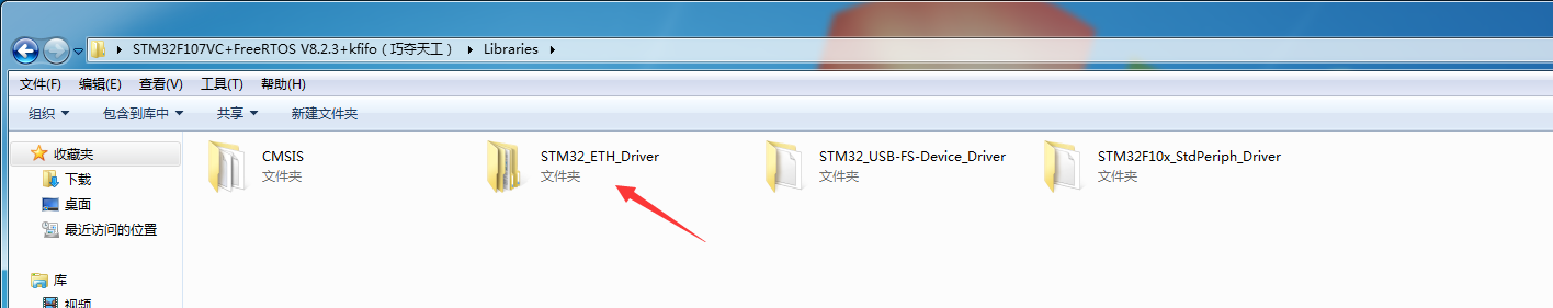
3、第三步:复制官方DEMO 文件目录(C:UsersadminDesktopSTM32F107_ETH_LwIP_V1.0.0Libraries)下的 STM32_ETH_Driver 文件到 你的 工程路径下,并添加到工程中。

我复制到 了 这个 路径。
添加到工程中:

第四步:新建 stm32f107_eth.c 文件 ,主要存放 STM32F107 和 DM9161 的 GPIO、DMA、MAC 的 寄存器 配置函数,下面代码分析:
(注意:以下几个函数都是在官方demo中 stm32f107.c 中 复制 和 稍作修改而来)
注意 在stm32f107_eth.c 文件 中 包含头文件:
#include "stm32_eth.h"
第一个函数:void stm32f107_eth_init(void);(直接在 main.c中调用)。


/**
  * @brief  Configures the Ethernet Interface
  * @param  None
  * @retval None
  */
void stm32f107_eth_init(void)
{

    GPIO_Configuration();

    Ethernet_Configuration();

}
第二个函数:void GPIO_Configuration(void); (STM32F107 和 DM9161 之间的接口是 RMII 接口,所以只配置 RMII接口所用到的引脚和时钟)。
/**
  * @brief  Configures the different GPIO ports.
  * @param  None
  * @retval None
    * 修改记录:因为选择的是ETH_RMII 接口,因此 屏蔽掉不必要的接口,这样,就不会引起其他引脚的问题!
  */
void GPIO_Configuration(void)
{
  GPIO_InitTypeDef GPIO_InitStructure;

      /* Enable GPIOs clocks */
  RCC_APB2PeriphClockCmd(RCC_APB2Periph_GPIOA | RCC_APB2Periph_GPIOB | RCC_APB2Periph_GPIOC |
                         RCC_APB2Periph_GPIOD| RCC_APB2Periph_AFIO , ENABLE);

  /* ETHERNET pins configuration */
  /* AF Output Push Pull:
  - ETH_MII_MDIO / ETH_RMII_MDIO: PA2
  - ETH_MII_MDC / ETH_RMII_MDC: PC1
  - ETH_MII_TXD2: PC2
  - ETH_MII_TX_EN / ETH_RMII_TX_EN: PB11
  - ETH_MII_TXD0 / ETH_RMII_TXD0: PB12
  - ETH_MII_TXD1 / ETH_RMII_TXD1: PB13
  - ETH_MII_PPS_OUT / ETH_RMII_PPS_OUT: PB5
  - ETH_MII_TXD3: PB8 */

  /* Configure PA2 as alternate function push-pull */
  GPIO_InitStructure.GPIO_Pin = GPIO_Pin_2;
  GPIO_InitStructure.GPIO_Speed = GPIO_Speed_50MHz;
  GPIO_InitStructure.GPIO_Mode = GPIO_Mode_AF_PP;
  GPIO_Init(GPIOA, &GPIO_InitStructure);

  /* Configure PC1, PC2 and PC3 as alternate function push-pull */
//  GPIO_InitStructure.GPIO_Pin = GPIO_Pin_1 | GPIO_Pin_2;
    GPIO_InitStructure.GPIO_Pin = GPIO_Pin_1 ;
  GPIO_InitStructure.GPIO_Speed = GPIO_Speed_50MHz;
  GPIO_InitStructure.GPIO_Mode = GPIO_Mode_AF_PP;
  GPIO_Init(GPIOC, &GPIO_InitStructure);

  /* Configure PB5, PB8, PB11, PB12 and PB13 as alternate function push-pull */
//  GPIO_InitStructure.GPIO_Pin = GPIO_Pin_5 | GPIO_Pin_8 | GPIO_Pin_11 | GPIO_Pin_12 | GPIO_Pin_13;
  GPIO_InitStructure.GPIO_Pin = GPIO_Pin_5 | GPIO_Pin_11 | GPIO_Pin_12 | GPIO_Pin_13;
  GPIO_InitStructure.GPIO_Speed = GPIO_Speed_50MHz;
  GPIO_InitStructure.GPIO_Mode = GPIO_Mode_AF_PP;
  GPIO_Init(GPIOB, &GPIO_InitStructure);

  /**************************************************************/
  /*               For Remapped Ethernet pins                   */
  /*************************************************************/
  /* Input (Reset Value):
  - ETH_MII_CRS CRS: PA0
  - ETH_MII_RX_CLK / ETH_RMII_REF_CLK: PA1
  - ETH_MII_COL: PA3
  - ETH_MII_RX_DV / ETH_RMII_CRS_DV: PD8
  - ETH_MII_TX_CLK: PC3
  - ETH_MII_RXD0 / ETH_RMII_RXD0: PD9
  - ETH_MII_RXD1 / ETH_RMII_RXD1: PD10
  - ETH_MII_RXD2: PD11
  - ETH_MII_RXD3: PD12
  - ETH_MII_RX_ER: PB10 */

  /* ETHERNET pins remapp in STM3210C-EVAL board: RX_DV and RxD[3:0] */
  GPIO_PinRemapConfig(GPIO_Remap_ETH, ENABLE);

  /* Configure PA0, PA1 and PA3 as input */
//  GPIO_InitStructure.GPIO_Pin = GPIO_Pin_0 | GPIO_Pin_1 | GPIO_Pin_3;
  GPIO_InitStructure.GPIO_Pin =  GPIO_Pin_1;
  GPIO_InitStructure.GPIO_Speed = GPIO_Speed_50MHz;
  GPIO_InitStructure.GPIO_Mode = GPIO_Mode_IN_FLOATING;
  GPIO_Init(GPIOA, &GPIO_InitStructure);

//  /* Configure PB10 as input */
//  GPIO_InitStructure.GPIO_Pin = GPIO_Pin_10;
//  GPIO_InitStructure.GPIO_Speed = GPIO_Speed_50MHz;
//  GPIO_InitStructure.GPIO_Mode = GPIO_Mode_IN_FLOATING;
//  GPIO_Init(GPIOB, &GPIO_InitStructure);

//  /* Configure PC3 as input */
//  GPIO_InitStructure.GPIO_Pin = GPIO_Pin_3;
//  GPIO_InitStructure.GPIO_Speed = GPIO_Speed_50MHz;
//  GPIO_InitStructure.GPIO_Mode = GPIO_Mode_IN_FLOATING;
//  GPIO_Init(GPIOC, &GPIO_InitStructure);

  /* Configure PD8, PD9, PD10, PD11 and PD12 as input */
//  GPIO_InitStructure.GPIO_Pin = GPIO_Pin_8 | GPIO_Pin_9 | GPIO_Pin_10 | GPIO_Pin_11 | GPIO_Pin_12;
  GPIO_InitStructure.GPIO_Pin = GPIO_Pin_8 | GPIO_Pin_9 | GPIO_Pin_10;
  GPIO_InitStructure.GPIO_Speed = GPIO_Speed_50MHz;
  GPIO_InitStructure.GPIO_Mode = GPIO_Mode_IN_FLOATING;
  GPIO_Init(GPIOD, &GPIO_InitStructure); /**/


  /* MCO pin configuration------------------------------------------------- */
  /* Configure MCO (PA8) as alternate function push-pull */
    /*需要STM32F107给DM9161提供 50MHZ 的 时钟*/
  GPIO_InitStructure.GPIO_Pin = GPIO_Pin_8;
  GPIO_InitStructure.GPIO_Speed = GPIO_Speed_50MHz;
  GPIO_InitStructure.GPIO_Mode = GPIO_Mode_AF_PP;
  GPIO_Init(GPIOA, &GPIO_InitStructure);

}
第三个函数:void Ethernet_Configuration(void); 注意要使用这个函数 要进行宏定义两个参数!
//因为选择 RMII 接口 (不懂的请百度)
#define RMII_MODE /* RMII mode for STM32107VC TO DM9161,2016年10月21日17:27:32 */
/* DM9161的物理地址是通过接收的4个脚26到29(与RXD3—RXD0复用)以及35脚CRS/PHYAD4来确定的。
* 具体来说,就是在上电复位的时候,根据这几个脚的高电平来确定地址。
* 比如我手头的板子上采用的RMMI,只接了RXD0,RXD1,其他几个脚空着,所以上电时只有RXD0与RXD1是高电平,
* 因此DM9161物理地址为3.
* 2016年10月21日19:21:19,ADD
*/
#define PHY_ADDRESS 0x03
/** * @brief Configures the Ethernet Interface * @param None * @retval None */ void Ethernet_Configuration(void) { ETH_InitTypeDef ETH_InitStructure; /* Enable ETHERNET clock */ RCC_AHBPeriphClockCmd(RCC_AHBPeriph_ETH_MAC | RCC_AHBPeriph_ETH_MAC_Tx | RCC_AHBPeriph_ETH_MAC_Rx, ENABLE); /* MII/RMII Media interface selection ------------------------------------------*/ #ifdef MII_MODE /* Mode MII with STM3210C-EVAL */ GPIO_ETH_MediaInterfaceConfig(GPIO_ETH_MediaInterface_MII); /* Get HSE clock = 25MHz on PA8 pin (MCO) */ RCC_MCOConfig(RCC_MCO_HSE); #elif defined RMII_MODE /* Mode RMII with STM3210C-EVAL */ GPIO_ETH_MediaInterfaceConfig(GPIO_ETH_MediaInterface_RMII); /* Set PLL3 clock output to 50MHz (25MHz /5 *10 =50MHz) */ RCC_PLL3Config(RCC_PLL3Mul_10); /* Enable PLL3 */ RCC_PLL3Cmd(ENABLE); /* Wait till PLL3 is ready */ while (RCC_GetFlagStatus(RCC_FLAG_PLL3RDY) == RESET) {} /* Get PLL3 clock on PA8 pin (MCO) */ RCC_MCOConfig(RCC_MCO_PLL3CLK); #endif /* Reset ETHERNET on AHB Bus */ ETH_DeInit(); /* Software reset */ ETH_SoftwareReset(); /* Wait for software reset */ while (ETH_GetSoftwareResetStatus() == SET); /* ETHERNET Configuration ------------------------------------------------------*/ /* Call ETH_StructInit if you don't like to configure all ETH_InitStructure parameter */ ETH_StructInit(Ð_InitStructure); /* Fill ETH_InitStructure parametrs */ /*------------------------ MAC -----------------------------------*/ ETH_InitStructure.ETH_AutoNegotiation = ETH_AutoNegotiation_Enable ; ETH_InitStructure.ETH_LoopbackMode = ETH_LoopbackMode_Disable; ETH_InitStructure.ETH_RetryTransmission = ETH_RetryTransmission_Disable; ETH_InitStructure.ETH_AutomaticPadCRCStrip = ETH_AutomaticPadCRCStrip_Disable; ETH_InitStructure.ETH_ReceiveAll = ETH_ReceiveAll_Disable; ETH_InitStructure.ETH_BroadcastFramesReception = ETH_BroadcastFramesReception_Enable; ETH_InitStructure.ETH_PromiscuousMode = ETH_PromiscuousMode_Disable; ETH_InitStructure.ETH_MulticastFramesFilter = ETH_MulticastFramesFilter_Perfect; ETH_InitStructure.ETH_UnicastFramesFilter = ETH_UnicastFramesFilter_Perfect; #ifdef CHECKSUM_BY_HARDWARE ETH_InitStructure.ETH_ChecksumOffload = ETH_ChecksumOffload_Enable; #endif /*------------------------ DMA -----------------------------------*/ /* When we use the Checksum offload feature, we need to enable the Store and Forward mode: the store and forward guarantee that a whole frame is stored in the FIFO, so the MAC can insert/verify the checksum, if the checksum is OK the DMA can handle the frame otherwise the frame is dropped */ ETH_InitStructure.ETH_DropTCPIPChecksumErrorFrame = ETH_DropTCPIPChecksumErrorFrame_Enable; ETH_InitStructure.ETH_ReceiveStoreForward = ETH_ReceiveStoreForward_Enable; ETH_InitStructure.ETH_TransmitStoreForward = ETH_TransmitStoreForward_Enable; ETH_InitStructure.ETH_ForwardErrorFrames = ETH_ForwardErrorFrames_Disable; ETH_InitStructure.ETH_ForwardUndersizedGoodFrames = ETH_ForwardUndersizedGoodFrames_Disable; ETH_InitStructure.ETH_SecondFrameOperate = ETH_SecondFrameOperate_Enable; ETH_InitStructure.ETH_AddressAlignedBeats = ETH_AddressAlignedBeats_Enable; ETH_InitStructure.ETH_FixedBurst = ETH_FixedBurst_Enable; ETH_InitStructure.ETH_RxDMABurstLength = ETH_RxDMABurstLength_32Beat; ETH_InitStructure.ETH_TxDMABurstLength = ETH_TxDMABurstLength_32Beat; ETH_InitStructure.ETH_DMAArbitration = ETH_DMAArbitration_RoundRobin_RxTx_2_1; /* Configure Ethernet */ ETH_Init(Ð_InitStructure, PHY_ADDRESS); /* Enable the Ethernet Rx Interrupt */ ETH_DMAITConfig(ETH_DMA_IT_NIS | ETH_DMA_IT_R, ENABLE); }
中断配置 和中断服务函数配置。
2016-10-21 20:01:08
第五步:移植LWIP协议
1、首先下载 lwip 源码,2016年10月22日17:44:25 最新源码的版本是:lwip-2.0.0.RC2.zip
下载地址:
http://download.savannah.gnu.org/releases/lwip/
2、下载ST官网 关于FreeRTOS和LWIP 在STM32F4X7上跑的 DEMO