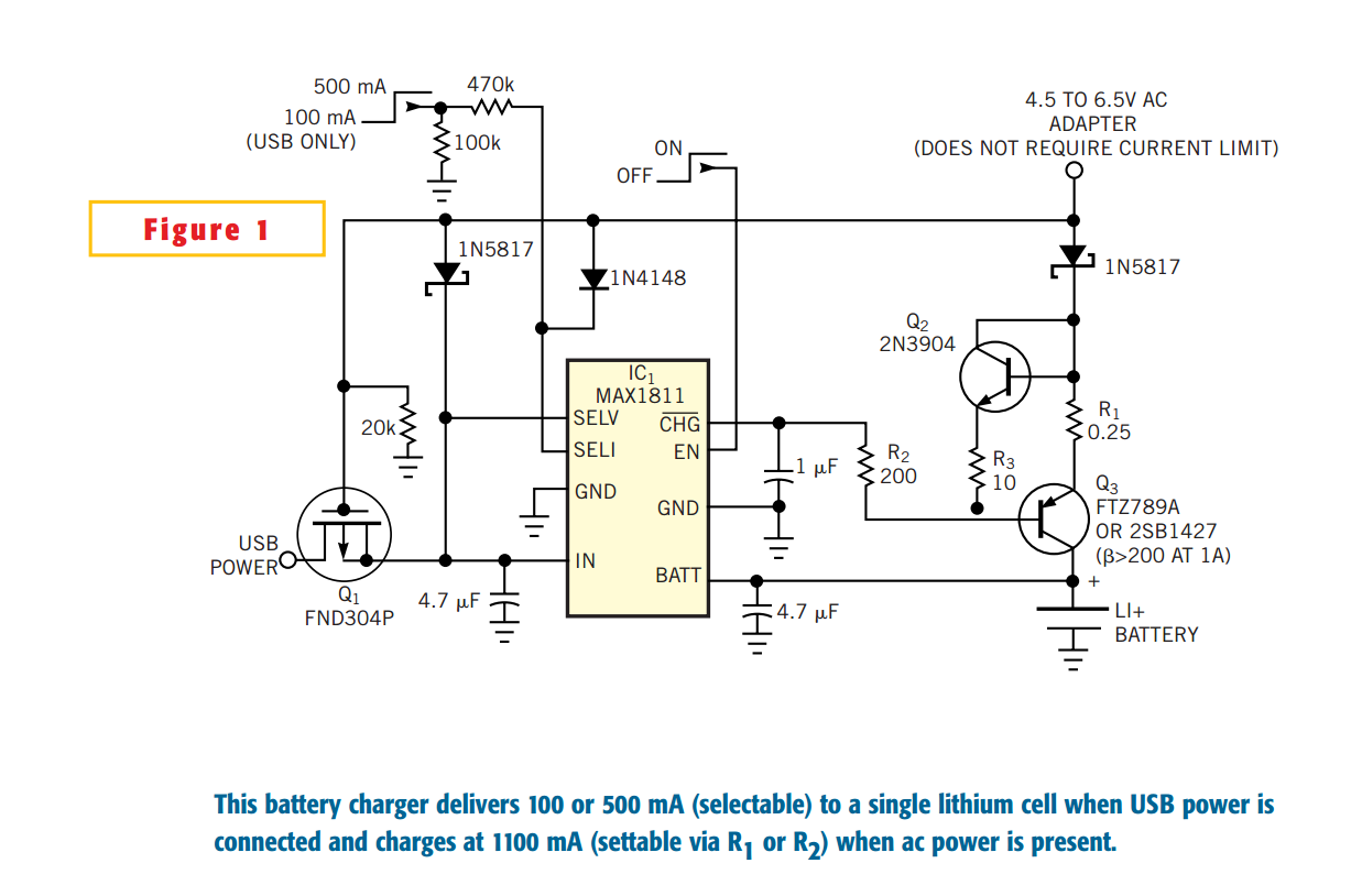
The popular USB interface can charge a portable device while transferring data. But for high-capacity batteries, the 500-mA output current of USB hosts and powered hubs greatly extends the charging time. (Unpowered USB hubs supply no more than 100 mA.) Thus, a system that accepts charging power from an ac adapter as well as the USB port is more convenient. Such a system can charge from a notebook USB port when you're traveling, yet can charge faster via the adapter when you're at home or in the office. An external transistor current source adds dual-input capability to a single-chip lithium-cell charger (Figure 1). The chip, IC1, operates alone when you connect to USB power and allows you to pin-program it for a maximum charging current of either 500 or 100 mA. When you plug in an ac adapter, which the 600-mA components set, the external-transistor current source, Q2 and Q3, turns on and sets IC1's charging current to 500 mA. Because IC1 and Q2 both charge the battery under that condition, the total charging current is 1100 mA.
Q2 and Q3 form a current limiter for the ac adapter. The limiter allows Q2 and R1 to pass the additional 600 mA. When the voltage drop across R1 exceeds that across R2, which R2 and R5 set, Q2 begins to turn off. Q2 cancels VBE, enabling R1 to more accurately set the maximum current. Voltage across R3 sets the reference voltage, and the output current limits when the voltage drop on R1 matches the voltage on R3. Q3should have a beta higher than 200 at 1A, so that IC1's ![]() pin can sink enough current to turn on Q3. High beta also minimizes error in the transistor current source. When IC1 changes from current mode to voltage mode at approximately 4.15V, IC1's
pin can sink enough current to turn on Q3. High beta also minimizes error in the transistor current source. When IC1 changes from current mode to voltage mode at approximately 4.15V, IC1's ![]() output turns off the transistor current source. IC1 remains on and finishes off the taper to full charge. It also remains on and continues to function when USB power is gone and only ac power remains.
output turns off the transistor current source. IC1 remains on and finishes off the taper to full charge. It also remains on and continues to function when USB power is gone and only ac power remains.
IC1 also controls the prequalification current, which is the current level necessary to safely recover deeply discharged cells at low battery voltage. The ![]() output assumes a high-impedance state during cell prequalification to ensure that the external current source remains off, and that the prequalification current of approximately 50 mA comes only from IC1. When you plug in the ac power, Q1 turns off to prevent back-feeding the USB input. You install Q1 "backward" with the drain connected to USB input side, so that USB power remains connected to the IN pin (IC1 pin 4) via Q1's body diode, even when Q1 is off.
output assumes a high-impedance state during cell prequalification to ensure that the external current source remains off, and that the prequalification current of approximately 50 mA comes only from IC1. When you plug in the ac power, Q1 turns off to prevent back-feeding the USB input. You install Q1 "backward" with the drain connected to USB input side, so that USB power remains connected to the IN pin (IC1 pin 4) via Q1's body diode, even when Q1 is off.