Industrial controls make heavy use of 4- to 20-mA current loops to transmit process measurements because current loops retain information in the presence of noise and changes in loop voltage. The loop circuit requires proper calibration to ensure accurate readings. The circuit in Figure 1 calibrates the loop by generating a current in response to a control voltage:
where IOUT is the output current, VCONTROL is the control voltage, RSENSE is the sense resistance, and KCSA is the gain of the current-sense amplifier—20 in this case. The circuit comprises IC2, a Maxim MAX5304 DAC; IC3, a MAX4376T current-sense amplifier; IC4, a MAX420 op amp; and Q1, an N-channel IRFL4105 MOSFET. The op amp lets the control voltage set the output current because it forces the voltage on the negative input equal to that on its positive input. The output current depends on the value of the sense resistor, the gain of the current-sense amplifier, and the control voltage.
The DAC provides the control voltage that lets you automate the calibration procedure. By selecting the right value for the sense resistor and by using a suitable resistor divider for R1 and R2 at the output of the DAC, you can adjust the circuit's output to 4 mA when the DAC's digital input is zero-scale and 20 mA when the digital input is full-scale.
Figure 1 shows the component values you need to achieve that condition.
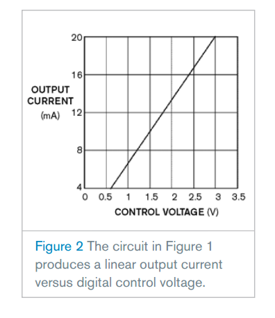
With a zero-sca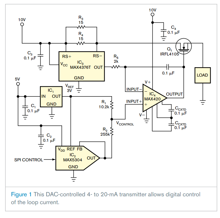 le digital input, the DAC output is 0V and the resistor divider produces 0.6V at the op amp's positive input, forcing the output current to 4 mA. With a full-scale digital input, both the DAC output and the midpoint of the resistor divider are at the 3V reference voltage, forcing the output current to 20 mA. A transfer curve relates the output current to the control voltage (Figure 2).