http://letsmakerobots.com/node/13843
Reading A Sensor With Higher Accuracy – RC Timing Method
RC Timing Method:
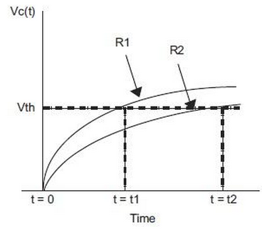
Simple RC step response
Vc(t) = VDD * (1 - e -t/(RC))
t = -RC ln(1 - Vth/VDD)
Vth/VDD is constant : R2 = (t2/t1) * R1
A reference resistor can be used to improve the accuracy of an analog sensor reading.
In this diagram, the charge time of a resistor/capacitor combination is measured using a timer and a port input or comparator input switches from a '0' to '1'.
The R1 curve uses a reference resistor and the R2 curve uses the sensor.
The charge time of the R1 curve is known and can be used to calibrate the unknown sensor reading, R2.
This reduces the affects of temperature, component tolerance and noise while reading the sensor.
Application Notes:
AN512 Implementing Ohmmeter/Temperature Sensor
AN611 Resistance and Capacitance Meter Using a PIC16C622
Ever find yourself in need of some extra ADC capabilities? Maybe you have a micro with no ADC built in, maybe you've used up all your ADC pins already, or maybe the integrated ADC doesn't provide a high enough resolution. This is where a custom-built Capacitor ADC can become very useful.
Now, there are ADC ICs that you can buy which will handle all the ADC stuff externally and just feed the digital results to your micro - there isn't anything wrong with these. If you can afford the cost and the PCB space then you can save yourself some time and effort by grabbing one of these. In my case however I had a small micro with no ADC, and if I added a big ADC IC to my circuit then what would be the point of having a small micro in the first place?
BTW, although I developed this particular method myself, I'm certainly not the first to use RC timing for ADC applications =)
If you are interested in some slightly more advanced stuff, I strongly recommend you check out the Microchip Tips n Tricks for 8-pin micros, which has many useful techniques that are applicable to small micros. As usual, Wikipedia also has a lot of good info on various ADC types.
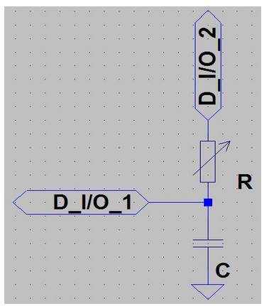
So here's the most basic example - 2 digital I/O pins, one resistive sensor, and one capacitor. I know 2 pins for one sensor isn't very good in terms of pin efficiency, but it scales favourably with more sensors, as the number of pins = number of sensors + 1.
The method for reading the sensor is as follows:
• Set D I/O 1 & 2 as outputs, with D I/O 1 -> LOW and D I/O 2 -> HIGH.
• Set D I/O 1 as an input.
• Start a timer.
• When D I/O 1 changes from reading LOW to HIGH, stop the timer and record the value.
The time it takes for D I/O 1 to go from LOW to HIGH is a function of the resistance of the sensor R. It's not a nice linear relationship, but for many applications this is far from important, especially if you're just using a few thresholds to analyse the sensor. If you were using this method with an LDR in place of R, where the resistance drops as more light hits the sensor, then you'd see smaller timer values as more light fell on the LDR.
You can extend this approach to virtually an infinite number of sensors, just by connecting them all to the same capacitor and reading them sequentially. When you're reading one sensor just follow the method above, and set all the other sensor D I/O pins to inputs - that way they won't interfere with the sensor you're reading.
One final note - I've just shown the basic technique for reading resistive sensors here, but you can do the same thing with semiconductor sensors (reverse-biased LEDs, photodiodes, phototransistors, etc) just by substituting R for the sensor. In some cases you may want to limit the sensor current with a fixed series resistor too.
Other types of sensors (such as RF antenna) can also be used with this technique, but you have to be able to use an I/O pin to 'disable' the sensor when you want to read the others. Often a few cleverly placed diodes or transistors will do the trick.