

General Introduction
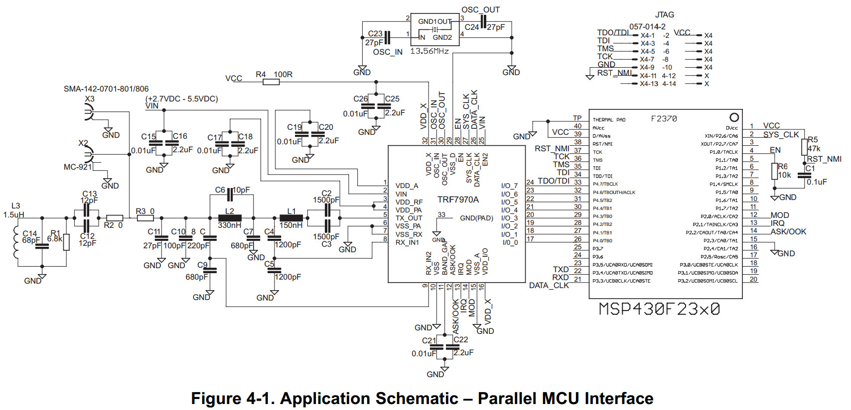
The communication interface to the reader can be configured in two ways:
with a eight line parallel interface (D0:D7) plus DATA_CLK, or
with a three or four wire Serial Peripheral Interface (SPI).
The SPI interface uses traditional Master Out/Slave In (MOSI), Master In/Slave Out (MISO), IRQ, and DATA_CLK lines.
The SPI can be operated with or without using the Slave Select line.
These communication modes are mutually exclusive; that is, only one mode can be used at a time in the application.
When the SPI interface is selected, the unused I/O_2, I/O_1, and I/O_0 pins must be hard-wired as shown in Table 5-9.
At power up, the TRF7970A samples the status of these three pins and then enters one of the possible SPI modes.
The TRF7970A always behaves as the slave device, and the microcontroller (MCU) behaves as the master device.
The MCU initiates all communications with the TRF7970A, and the TRF7970A makes use of the Interrupt Request (IRQ) pin
in both parallel and SPI modes to prompt the MCU for servicing attention.
Communication is initialized by a start condition, which is expected to be followed by an Address/Command word (Adr/Cmd).
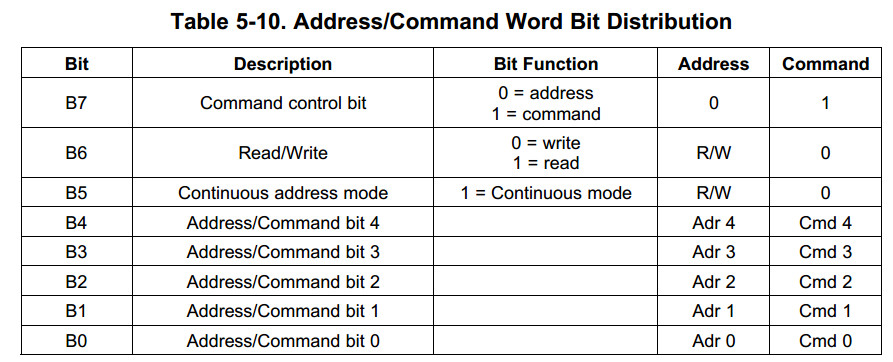
The Adr/Cmd word is 8 bits long, and its format is shown in Table 5-10.
The MSB (bit 7) determines if the word is to be used as a command or as an address.
The last two columns of Table 5-10 show the function of the separate bits if either address or command is written.
Data is expected once the address word is sent.
In continuous-address mode (Cont. mode = 1), the first data that follows the address is written (or read) to (from) the given address.
For each additional data, the address is incremented by one.
Continuous mode can be used to write to a block of control registers in a single stream without changing the address;
for example, setup of the predefined standard control registers from the MCU non-volatile memory to the reader.
In non-continuous address mode (simple addressed mode), only one data word is expected after the address.
Address Mode is used to write or read the configuration registers or the FIFO. When writing more than 12 bytes to the FIFO,
the Continuous Address Mode should be set to 1.
The Command Mode is used to enter a command resulting in reader action
(for example, initialize transmission, enable reader, and turn reader on or off).
Examples of expected communications between an MCU and the TRF7970A are shown in the following sections.
The IRQ line is indeed the interrupt back to the MCU to indicate something has occurred. The reading of the IRQ status register is then the pointer to the logic of what to do next. For example, after transmitting out a command sequence to a tag, you will get an IRQ which needs to be serviced by reading the IRQ status register (which clears the IRQ), then most likely you would have an 0x80, telling you that the transmission was successful (we call EOTX (end of transmit) IRQ)...then you would next get an IRQ, which would for example be 0x40, indicating an EORX (end of recieve) has occured, then you would read the FIFO status for # of bytes to clock out, then read the FIFO for the data...you can see in the data sheet the descriptions of the IRQ register and and some examples, too. (see the TRF7970A DS, section 5.9.xx)
The ASK/OOK line in your case most likely can just be pulled to GND or you can connect it to a GPIO on your MCU like we have it shown in the reference schematics. MOD same thing, unless you are using any Mifare Classic tags, then you would need control of the MOD pin for Direct Mode 0, so then it would need to be connected to a GPIO.
Usually we are recommending connecting EN line to a GPIO, with a pulldown (needs to see low to high transition) so you can have control of some of the power modes...EN2 can also be connected to a GPIO or pulled high or low, depending on your need for even lower power consumption.
Correct about I/O_0, I/O_1 and I/O_2 being at GND potential for SPI w/o SS.
If it helps here is a schematic of SPI with SS, which you can modify for your own usage, since you say you want to do without SS. (I/O_3 and I/O_5 are connected in this drawing as well, and this is for Special Direct Mode, which you may or may not need, depending on which tags you are trying to use here - normally not needed, just FYI)
7183.TRF7970A_SPI_MSP430F2370_dongle_sch.pdf
