http://www.ethernut.de/en/hardware/turtelizer/
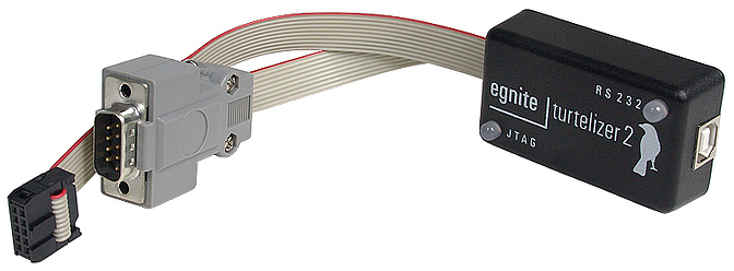
Introducing Turtelizer 2
Overview
Turtelizer 2 had been developed to provide JTAG Flash programming and debugging of ARM based boards via USB. Typical target boards are Ethernut 3 , the Elektor Internet Radio or Ethernut 5. However, as the hardware is based on the FT2232 chip from www.ftdichip.com, it offers a general JTAG, SPI, I2C and RS 232 capabilities.
This document will present the open source hardware design and some basic information how to get it up and running. Several links to external resources are given, where specific topics are discussed in detail. It is intended for hardware developers, who want to build their own FTDI based JTAG dongle.
If you bought a ready-to-run Turtelizer dongle or any of its clones and just want to know, how to use it for programming and debugging your target board, then theTurtelizer 2 User's Guide is the right document for you.
Features
-
Fully buffered JTAG interface for target voltages from 1.65V to 5.5V.
-
Additional RS 232 Interface with virtual COM port driver.
-
Space saving 10-pin JTAG connector. Standard 14-pin and 20-pin connectors require an adapter.
-
Open Source hardware and software. Supported by OpenOCD and YAGARTO and tested on Linux, Mac OS X and Windows.
Requirements
Most tools used here to get the Turtelizer hardware up and running are available for Windows only, specifically the MProg Tool.
Once configured, the Turtelizer can be used on Mac OS X, Linux and Windows PCs.
Open Source Hardware Copyright
Copyright (C) by egnite GmbH
Redistribution and use of the layout itself or products based on this design, with or without modification, are permitted provided that the following conditions are met:
- Redistributions of the layout must retain the above copyright notice, this list of conditions and the following disclaimer.
- Redistributions of hardware products based on this design must reproduce the above copyright notice, this list of conditions and the following disclaimer in the documentation and/or other materials provided with the distribution.
THIS HARDWARE DESIGN IS PROVIDED BY EGNITE SOFTWARE GMBH AND CONTRIBUTORS ``AS IS'' AND ANY EXPRESS OR IMPLIED WARRANTIES, INCLUDING, BUT NOT LIMITED TO, THE IMPLIED WARRANTIES OF MERCHANTABILITY AND FITNESS FOR A PARTICULAR PURPOSE ARE DISCLAIMED. IN NO EVENT SHALL EGNITE SOFTWARE GMBH OR CONTRIBUTORS BE LIABLE FOR ANY DIRECT, INDIRECT, INCIDENTAL, SPECIAL, EXEMPLARY, OR CONSEQUENTIAL DAMAGES (INCLUDING, BUT NOT LIMITED TO, PROCUREMENT OF SUBSTITUTE GOODS OR SERVICES; LOSS OF USE, DATA, OR PROFITS; OR BUSINESS INTERRUPTION) HOWEVER CAUSED AND ON ANY THEORY OF LIABILITY, WHETHER IN CONTRACT, STRICT LIABILITY, OR TORT (INCLUDING NEGLIGENCE OR OTHERWISE) ARISING IN ANY WAY OUT OF THE USE OF THIS DESIGN, EVEN IF ADVISED OF THE POSSIBILITY OF SUCH DAMAGE.
In simple words, you can use this layout for your personal use or for a commercial product free of charge.
If you want to pay for it, I'd suggest to donate a small amount to the OpenOCD.
Important Legal Notes
Some time ago a discussion came up in the OpenOCD development mailing list about whether it is legal to distribute a binary version of OpenOCD, which is linked to the proprietary library FTD2XX provided by FTDI. The result in one short sentence: It violates the GPL, under which OpenOCD is released.
This does not mean that OpenOCD stops workingwith Turtelizer 2. One alternative is to use the free library libftdi as a replacement for the FTD2XX library. However, there are some disadvantages:
- libftdi had been reported to be up to 2.5x slower than its closed source counterpart.
- The serial port on the Turtelizer will no longer work.
- libftdi will not work on 64-bit Windows.
Hopefully upcoming versions of libftdi will overcome these limitations. What can be done in the meantime?
The GPL regulates distribution of software, not its usage. For your own personal use it is allowed to create a version of OpenOCD that is linked with proprietary code. For Linux and OS X users this is typically no problem. Unfortunately, building OpenOCD from source code on Windows PCs is not trivial and requires a number of additional tools. Most unexperienced users will probably fail.
We decided to provide a pragmatic solution by seperating OpenOCD and the FTDI driver. You can find both packets on egnite's product page.
It is not allowed to distribute OpenOCD and the Turtelizer USB driver in a single package. Always keep them seperated.
Turtelizer 2 Hardware
PCB Version 2.0 Revision C
This is the current board revision. Compared to Rev-B, the following changes apply:
While it had been claimed, that Rev-B boards support target voltages down to 1.65V, it turned out, that this was out of specs. In fact, target voltages below 2.5V tend to work unreliable. This has been fixed in Rev-C by replacing two push-pull drivers NC7SZ125P5X (IC6 and IC8) with a single NC7WZ07P6X open collector driver.
An additional signal nTRST had been added to pin 8 of the JTAG connector. In the previous revision this pin was left unconnected.
IC2 FT2232L went out of production and had been replaced by its pin-compatible successor FT2232D. Pins SI/WUA and SI/WUB had been left floating in the previous revision, but are now tied to VCC as recommended in later data sheets.
The input pin FORCEOFF at the RS-232 driver is now connected to the SLEEP output of IC2. This forces the RS-232 driver to power-down after USB suspend. Furthermore, FORCEON of the RS-232 driver is now tied to VCC (permanently enabled) to allow to connect to low power devices.
All series resistors had been changed from 22Ω to 27Ω.
An RC-circuit had been added between digital ground and shield.
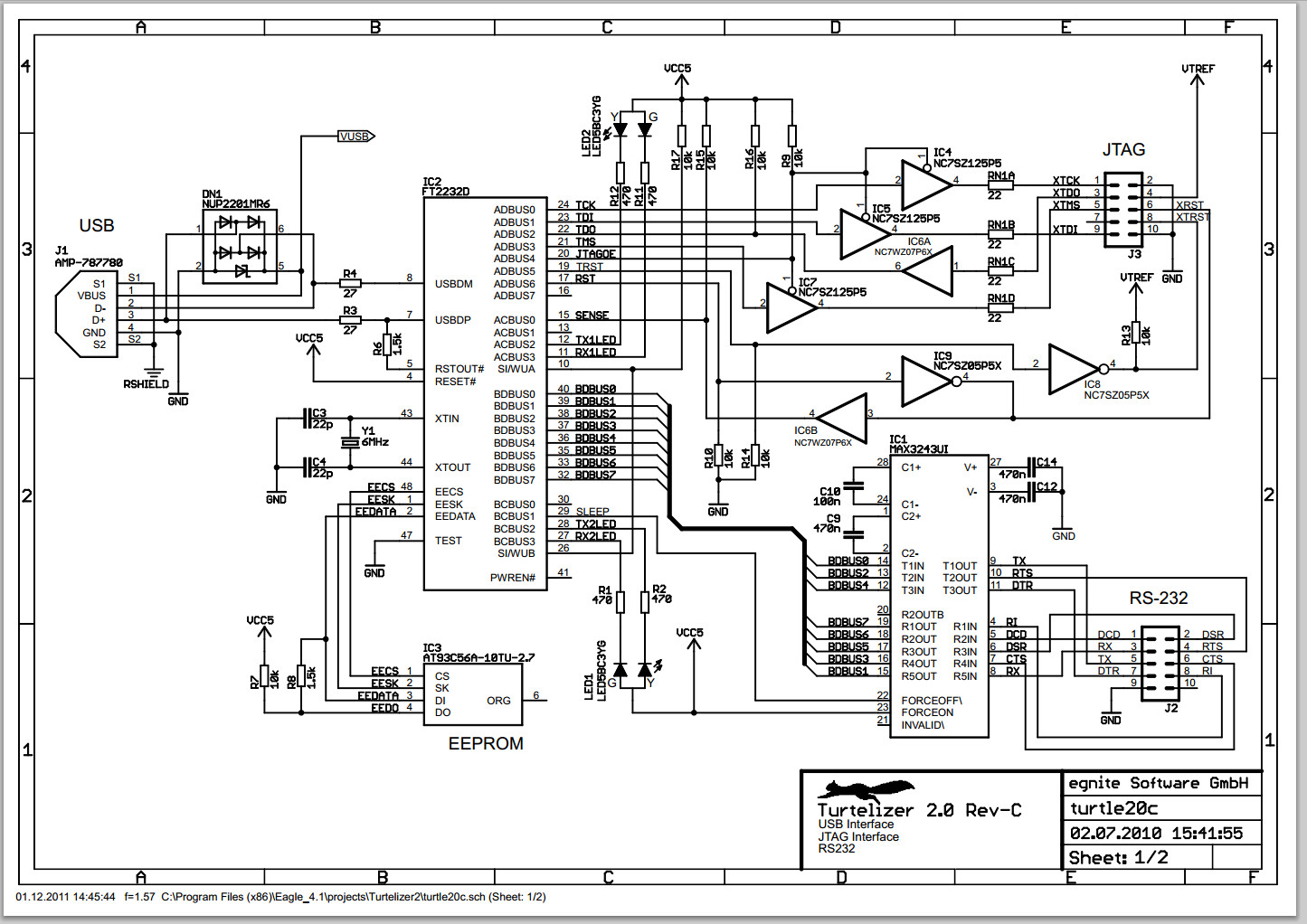
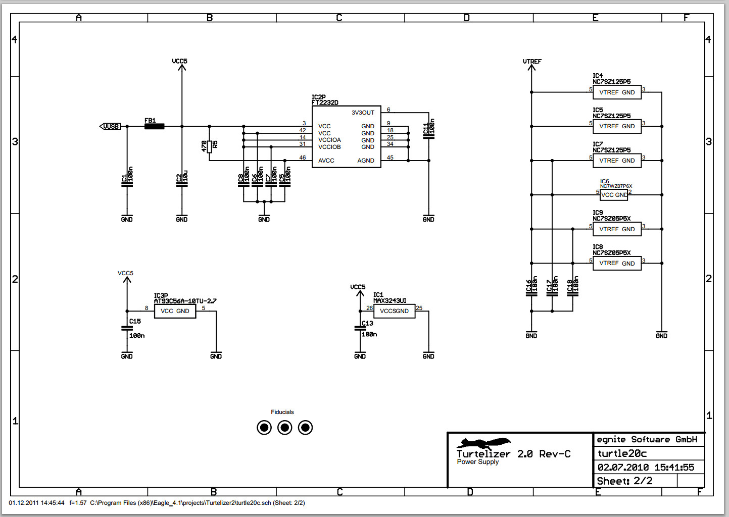
- Turtelizer 2.0 Rev-C Schematic
- Turtelizer 2.0 Rev-C CAD files: Can be viewed with the Freeware Version from Cadsoft.
PCB Version 2.0 Revision B
This was the first published revision.
Schematic Page 1: USB, JTAG and RS232 interface.
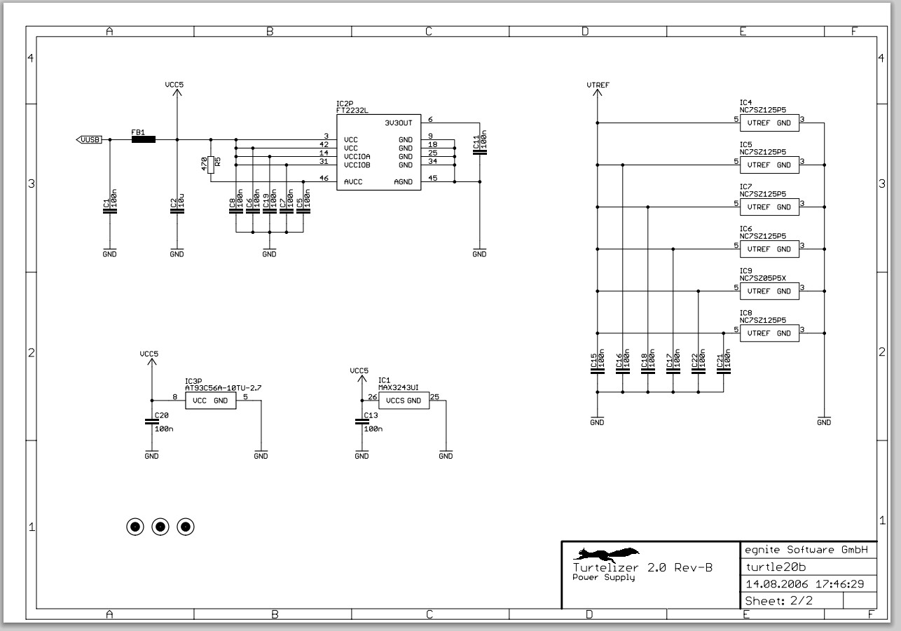
Schematic Page 2: Power Supply.
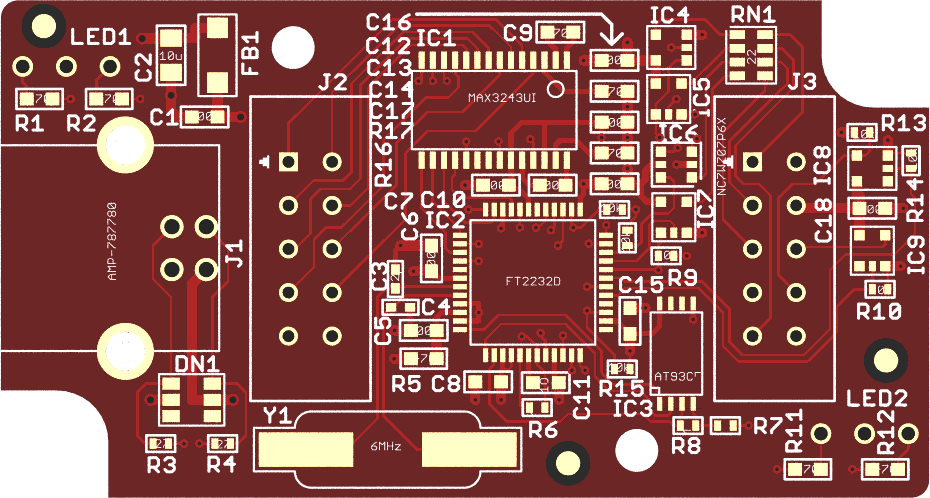
Board Layout: Fits in Hammond 1551H. enclosure.
turtle20b.zip : Eagle CAD Files. Can be viewed with the Freeware Version from Cadsoft.
All parts are available in RoHS compliant versions.
USB Interface
For detailed information about the FT2232 USB controller, please visit www.ftdichip.com. An Atmel AT93C56 EEPROM is used to store the configuration data.
A USB type B connector is mounted on the PCB (Tyco 292304 or similar). Power supply for the USB controller and the RS 232 driver is drawn from USB. A transient voltage suppressor array is used to protect the circuit from ESD and a ferrite bead suppresses noise in the power supply line.
JTAG Interface
A 10-pin female header connector is attached to the PCB via a ribbon cable, which is kept short to avoid problems at high transfer rates. The following table shows the connector layout.
| Turtelizer 2 JTAG Connector | |
|---|---|
| TCK - 1 | 2 - GND |
| TDO - 3 | 4 - VTref |
| TMS - 5 | 6 - nSRST |
| Vsupply - 7 | 8 - NC |
| TDI - 9 | 10 - GND |
All JTAG signals are buffered by LCX type single logic gates, which are powered by the JTAG VTref line. This way, the JTAG interface is automatically adjusted to different target voltage levels from 5.5V down to 1.65V. Additional series resistors in the JTAG lines help to maintain signal integrity and even provide some limited overvoltage protection.
RS 232 Interface
A second ribbon cable is used to attach a 9-pin male DSub connector for the RS 232 interface.
| Turtelizer 2 RS 232 Connector | |
|---|---|
| DCD - 1 | |
| 6 - DSR | |
| RD - 2 | |
| 7 - RTS | |
| TD - 3 | |
| 8 - CTS | |
| DTR - 4 | |
| 9 - RI | |
| GND - 5 | |
LED Indicators
Two 3-pin dual color LEDs with common anode are mounted on the back side of the PCB. LED1 indicates JTAG activity. LED2 is lit green when RS 232 data is received and lit red on RS 232 transmits.
JTAG Adapter
Using Turtelizer 2 with standard 14-pin or 20-pin JTAG connectors requires a
Special Adapter.
PCB Version 2.0 Revision B