高通lk:配置与使用i2c
以msm8909为例。
背景
在lk中要去驱动一个aw9523的ic来控制指示灯。
但是现在对应的i2c没有打开。因此需要进行处理。
步骤
找到I2C对应的ID与句柄
参考文档:80-nu767-1_l_bam_low-speed_peripherals_(blsp)_user_guide.pdf
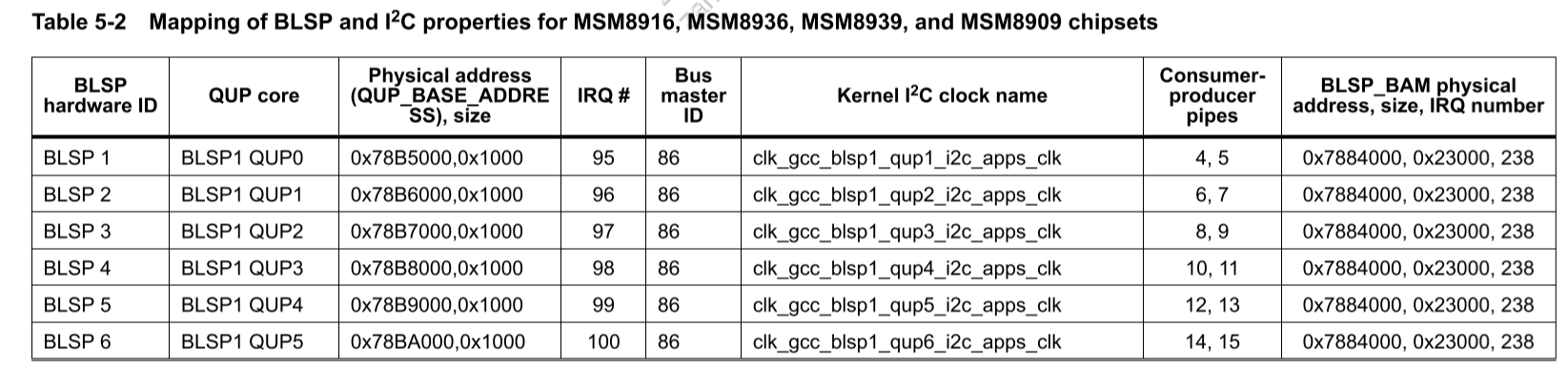
根据其他人的说法,i2c-1对应的是第一个BLSP1、QUP0、0x78B5000。
添加有关的时钟
路径:bootable/bootloader/lk/platform/msm8909/msm8909-clock.c
+
+// i2c-1
+static struct clk_freq_tbl ftbl_gcc_blsp1_qup1_i2c_apps_clk_src[] =
+{
+	F(      96000,    cxo,  10,   1,  2),
+	F(    4800000,    cxo,   4,   0,  0),
+	F(    9600000,    cxo,   2,   0,  0),
+	F(   16000000,  gpll0,  10,   1,  5),
+	F(   19200000,  cxo,   1,   0,  0),
+	F(   25000000,  gpll0,  16,   1,  2),
+	F(   50000000,  gpll0,  16,   0,  0),
+	F_END
+};
+
+static struct rcg_clk gcc_blsp1_qup1_i2c_apps_clk_src =
+{
+	.cmd_reg      = (uint32_t *) GCC_BLSP1_QUP1_CMD_RCGR,
+	.cfg_reg      = (uint32_t *) GCC_BLSP1_QUP1_CFG_RCGR,
+	.set_rate     = clock_lib2_rcg_set_rate_hid,
+	.freq_tbl     = ftbl_gcc_blsp1_qup1_i2c_apps_clk_src,
+	.current_freq = &rcg_dummy_freq,
+
+	.c = {
+		.dbg_name = "gcc_blsp1_qup1_i2c_apps_clk_src",
+		.ops      = &clk_ops_rcg,
+	},
+};
+
+static struct branch_clk gcc_blsp1_qup1_i2c_apps_clk = {
+	.cbcr_reg = GCC_BLSP1_QUP1_APPS_CBCR,
+	.parent   = &gcc_blsp1_qup1_i2c_apps_clk_src.c,
+
+	.c = {
+		.dbg_name = "gcc_blsp1_qup1_i2c_apps_clk",
+		.ops      = &clk_ops_branch,
+	},
+};
+

 static struct rcg_clk gcc_blsp1_qup2_i2c_apps_clk_src =
 {
@@ -585,6 +623,11 @@ static struct clk_lookup msm_clocks_msm8909[] =
 	CLK_LOOKUP("gcc_blsp1_qup2_i2c_apps_clk", gcc_blsp1_qup2_i2c_apps_clk.c),


+	// i2c-1
+	CLK_LOOKUP("blsp1_qup1_ahb_iface_clk", gcc_blsp1_ahb_clk.c),
+	CLK_LOOKUP("gcc_blsp1_qup1_i2c_apps_clk_src", gcc_blsp1_qup1_i2c_apps_clk_src.c),
+	CLK_LOOKUP("gcc_blsp1_qup1_i2c_apps_clk", gcc_blsp1_qup1_i2c_apps_clk.c),
+
 	CLK_LOOKUP("mdp_ahb_clk", mdp_ahb_clk.c),
 	CLK_LOOKUP("mdss_esc0_clk", mdss_esc0_clk.c),
 	CLK_LOOKUP("mdss_axi_clk", mdss_axi_clk.c),
初始化
+static void i2c1_init(void)
+{
+    static int flag = 1;
+
+    dprintf(CRITICAL, "%s : start
", __func__);
+    if(flag != 1)
+        goto end;
+    flag = 0;
+    // i2c-1
+   /*
+        1 arg: BLSP ID can be BLSP_ID_1 or BLSP_ID_2
+        2 arg: QUP ID can be QUP_ID_0 ~ QUP_ID_5
+        3 arg: I2C CLK. should be 100KHZ, or 400KHz
+        4 arg: Source clock, should be set @ 19.2MHz
+        */
+    i2c_dev = qup_blsp_i2c_init(BLSP_ID_1, QUP_ID_0, 100000, 19200000);
+    if(!i2c_dev)
+        dprintf(CRITICAL, "qup_blsp_i2c_init failed
");
+end :
+    dprintf(CRITICAL, "%s : end
", __func__);
+
+}
确保底层的调用没问题:
路径:bootable/bootloader/lk/platform/msm8909/acpuclock.c
/* Configure i2c clock */
void clock_config_blsp_i2c(uint8_t blsp_id, uint8_t qup_id)
{
    uint8_t ret = 0;
    char clk_name[64];

    struct clk *qup_clk;

    if((blsp_id != BLSP_ID_1) || (qup_id > QUP_ID_5)) {
        dprintf(CRITICAL, "Incorrect BLSP-%d or QUP-%d configuration
", blsp_id, qup_id);
        ASSERT(0);
    }

    snprintf(clk_name, sizeof(clk_name), "blsp1_qup1_ahb_iface_clk");

    ret = clk_get_set_enable(clk_name, 0 , 1);

    if (ret) {
        dprintf(CRITICAL, "Failed to enable %s clock
", clk_name);
        return;
    }

    snprintf(clk_name, sizeof(clk_name), "gcc_blsp1_qup1_i2c_apps_clk");

    qup_clk = clk_get(clk_name);

    if (!qup_clk) {
        dprintf(CRITICAL, "Failed to get %s
", clk_name);
        return;
    }

    ret = clk_enable(qup_clk);

    if (ret) {
        dprintf(CRITICAL, "Failed to enable %s
", clk_name);
        return;
    }
}
如果匹配不上的话,会导致下面错误:
Alert!! Requested clock "blsp1_qup1_ahb_iface_clk" is not supported![1140] [1140] Can't find clock with id: blsp1_qup1_ahb_iface_clk
读/写
+static int write_reg(uint8_t slave_addr, uint8_t reg, uint8_t val)
+{
+ int ret = 0;
+ uint8_t data_buf[] = { reg, val };
+
+ /* Create a i2c_msg buffer, that is used to put the controller into write
+ mode and then to write some data. */
+ struct i2c_msg msg_buf[] = { {slave_addr, I2C_M_WR, 2, data_buf} };
+
+ ret = qup_i2c_xfer(i2c_dev, msg_buf, 1);
+ if(ret < 0) {
+ dprintf(CRITICAL, "qup_i2c_xfer error %d
", ret);
+ return ret;
+ }
+ return 0;
+}
+
+static int read_reg(uint8_t slave_addr, uint8_t reg, uint8_t *val)
+{
+ int ret = 0;
+ /* Create a i2c_msg buffer, that is used to put the controller into read
+ mode and then to read some data. */
+ struct i2c_msg msg_buf[] = {
+ {slave_addr, I2C_M_WR, 1, ®},
+ {slave_addr, I2C_M_RD, 1, val}
+ };
+
+ ret = qup_i2c_xfer(i2c_dev, msg_buf, 2);
+ if(ret < 0) {
+ dprintf(CRITICAL, "qup_i2c_xfer error %d
", ret);
+ return ret;
+ }
+ return 0;
+}