名词
Extensible Linking Format(ELF)
3.1 The structure of an ARM ELF image
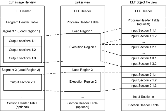
ARM ELF映像包含sections, regions, and segments,每个链接阶段都有不同的映像视图。
-
Number of its constituent regions and output sections.
-
Positions in memory of these regions and sections when the image is loaded.
-
Positions in memory of these regions and sections when the image executes.
- ELF object file view (linker input)
-
The ELF object file view comprises包含 input sections. The ELF object file can be:
-
A relocatable( 浮动的) file that holds code and data suitable for linking with other object files to create an executable or a shared object file.
-
A shared object file that holds code and data.
-
- Linker view
-
The linker has two views for the address space of a program that become distinct in the presence of overlaid(覆盖层的存在), position-independent, and relocatable program fragments (code or data):
-
The load address of a program fragment is the target address that the linker expects an external agent such as a program loader, dynamic linker, or debugger to copy the fragment from the ELF file. This might not be the address at which the fragment executes.
-
The execution address of a program fragment is the target address where the linker expects the fragment to reside(属于,归于) whenever it participates(参加) in the execution of the program.
If a fragment is position-independent or relocatable, its execution address can vary during execution. -
- ELF image file view (linker output)
-
The ELF image file view comprises program segments and output sections:
-
A load region corresponds to a program segment.
-
An execution region contains one or more of the following output sections:
- RO section.
- RW section.
- XO section.
- ZI section.
One or more execution regions make up a load region. -
Note
-
The term root region means a region that has the same load and execution addresses.
-
Load regions are equivalent to ELF segments.
3.2 Input sections, output sections, regions, and program segments
An object or image file is constructed from a hierarchy of input sections, output sections, regions, and program segments.
- Input section
-
An input section is an individual section from an input object file. It contains code, initialized data, or describes a fragment of memory that is not initialized or that must be set to zero before the image can execute. These properties are represented by attributes such as RO, RW, XO, and ZI. These attributes are used by armlink to group input sections into bigger building blocks called output sections and regions.
- Output section
-
An output section is a group of input sections that have the same RO, RW, XO, or ZI attribute, and that are placed contiguously in memory by the linker. An output section has the same attributes as its constituent input sections. Within an output section, the input sections are sorted according to the section placement rules.
- Region
-
A region contains up to four output sections depending on the contents and the number of sections with different attributes. By default, the output sections in a region are sorted according to their attributes. Any XO output section is first, followed by the RO output section, then the RW output section, and finally the ZI output section. A region typically maps onto a physical memory device, such as ROM, RAM, or peripheral. You can change the order of output sections using scatter-loading.
- Program segment
-
A program segment corresponds to a load region and contains execution regions. Program segments hold information such as text and data.
3.3 Load view and execution view of an image
Image regions are placed in the system memory map at load time. The location of the regions in memory might change during execution.
- Load view
-
Describes each image region and section in terms of the address where it is located when the image is loaded into memory, that is, the location before image execution starts.
- Execution view
-
Describes each image region and section in terms of the address where it is located during image execution.

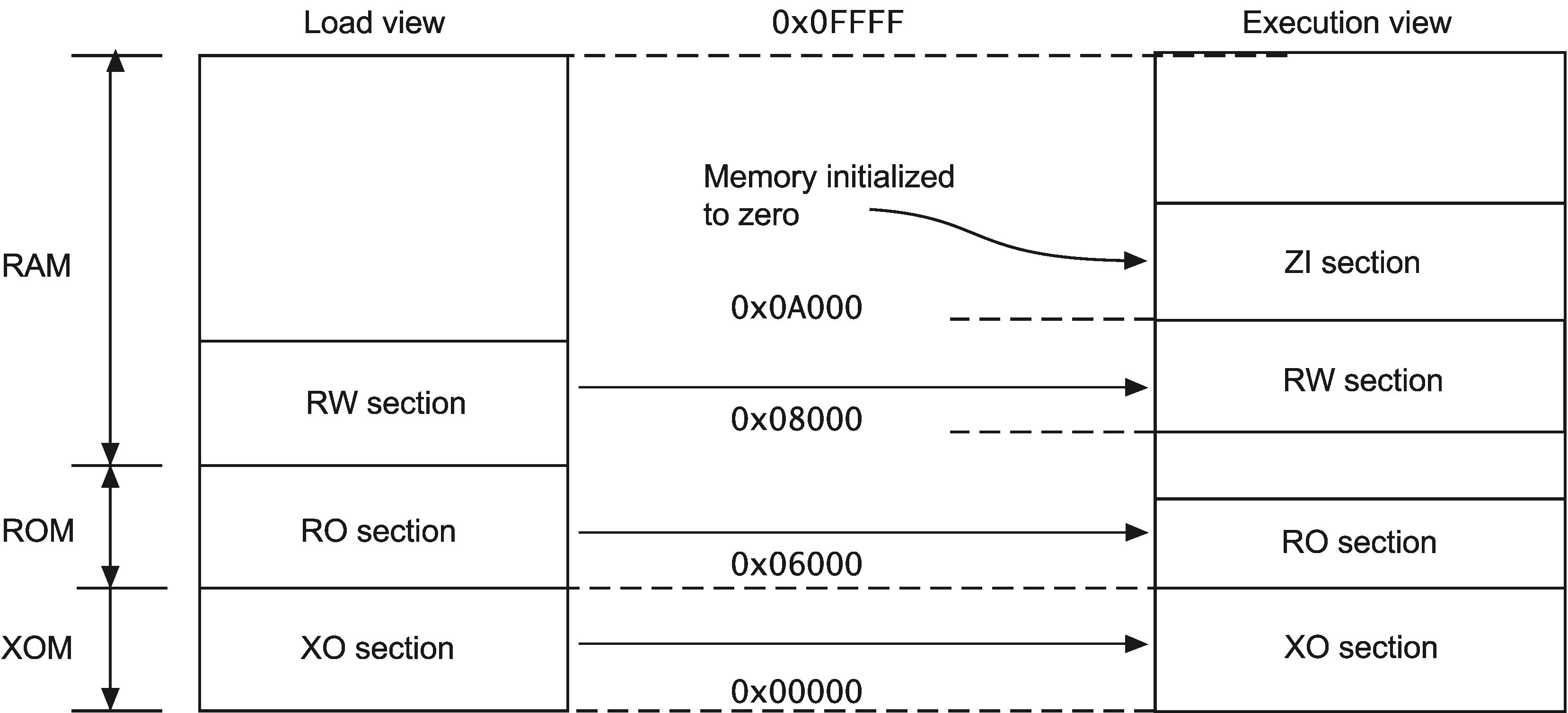
Table 3-1 Comparing load and execution views
| Load | Description | Execution | Description |
|---|---|---|---|
| Load address | The address where a section or region is loaded into memory before the image containing it starts executing. The load address of a section or a non-root region can differ from its execution address | Execution address | The address where a section or region is located while the image containing it is being executed |
| Load region | A load region describes the layout of a contiguous chunk of memory in load address space. | Execution region | An execution region describes the layout of a contiguous chunk of memory in execution address space. |
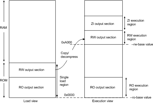
3.6 Type 1 image structure, one load region and contiguous execution regions
A Type 1 image consists of a single load region in the load view and three execution regions placed contiguously in the memory map.

armlink --ro_base 0x8000
Note
0x8000 is the default address, so you do not have to specify --ro_base for the example.Load view
Execution view
--ro_base address to specify the load and execution address of the region containing the RO output. The default address is 0x8000.--zi_base command-line option to specify the base address of a ZI execution region.Load view for images containing execute-only regions
--ro_base. The RO and RW output sections are placed consecutively and immediately after the XO section.Execution view for images containing execute-only regions
--ro_base. The RO, RW, and ZI execution regions are placed contiguously and immediately after the XO execution region.3.7 Type 2 image structure, one load region and non-contiguous execution regions
A Type 2 image consists of a single load region, and three execution regions in execution view. The RW execution region is not contiguous with the RO execution region.
armlink --ro_base 0x0 --rw_base 0xA000
Load view
Execution view
--ro_base address to specify the load and execution address for the RO output section, and --rw_base address to specify the execution address of the RW output section. If you do not use the --ro_base option to specify the address, the default value of 0x8000 is used by armlink. For an embedded system, 0x0 is typical for the --ro_base value. If you do not use the --rw_base option to specify the address, the default is to place RW directly above RO (as in a Type 1 image).--zi_base command-line option to specify the base address of a ZI execution region.Note
Load view for images containing execute-only regions
--ro_base. The RO and RW output sections are placed consecutively and immediately after the XO section.Execution view for images containing execute-only regions
--ro_base. The RO execution region is placed contiguously and immediately after the XO execution region.--xo_base address, then the XO execution region is placed in a separate load region at the specified address.3.8 Type 3 image structure, multiple load regions and non-contiguous execution regions
A Type 3 image is similar to a Type 2 image except that the single load region is split into multiple root load regions.

armlink --split --ro_base 0x8000 --rw_base 0xE000
Load view
Execution view
--ro_baseaddress-
Instructs armlink to set the load and execution address of the region containing the RO section at a four-byte aligned
address, for example, the address of the first location in ROM. If you do not use the--ro_baseoption to specify the address, the default value of0x8000is used byarmlink. --rw_baseaddress-
Instructs armlink to set the execution address of the region containing the RW output section at a four-byte aligned
address. If this option is used with--split, this specifies both the load and execution addresses of the RW region, for example, a root region. --split-
Splits the default single load region, that contains both the RO and RW output sections, into two root load regions:
-
One containing the RO output section.
-
One containing the RW output section.
You can then place them separately using--ro_baseand--rw_base. -
Load view for images containing XO sections
--ro_base. The RO and RW output sections are placed consecutively and immediately after the XO section.--split, then the one load region contains the XO and RO output sections, and the other contains the RW output section.Execution view for images containing XO sections
--ro_base. The RO execution region is placed contiguously and immediately after the XO execution region.--split, then the XO and RO execution regions are placed in the first load region, and the RW and ZI execution regions are placed in the second load region.--xo_base address, then the XO execution region is placed at the specified address in a separate load region from the RO execution region.3.11 Section placement with the linker
The linker places input sections in a specific order by default.
-
By attribute as follows:
-
Read-only code.
-
Read-only data.
-
Read-write code.
-
Read-write data.
-
Zero-initialized data.
-
-
By input section name if they have the same attributes. Names are considered to be case-sensitive and are compared in alphabetical order using the ASCII collation sequence for characters.
-
By a tie-breaker if they have the same attributes and section names. By default, it is the order that armlink processes the section. You can override this with the
FIRSTorLASTexecution region attribute.
Note
--tiebreaker=cmdline option uses a more predictable order based on the order the section appears on the command line.-
One execute-only (XO) section if the execution region contains only XO sections.
-
One RO section if the execution region contains read-only code or data.
-
One RW section if the execution region contains read-write code or data.
-
One ZI section if the execution region contains Zero-initialized data.
Note
--sort=algorithm command-line option. The linker might change the algorithm to minimize the amount of veneers generated if no algorithm is chosen.Handling unassigned sections
-
If the sections must be placed at specific locations, then modify your scatter file to include specific module selectors and input section selectors as required.
-
If the placement of the unassigned sections is not important, you can use one or more
.ANYmodule selectors with optional input section selectors.
Examples
LoadRegion 0x8000
{
    ExecRegion1 0x0000 0x4000
    {
        *(sections)
        *(moresections)
    }
    ExecRegion2 0x4000 0x2000
    {
        *(evenmoresections)
    }
}
3.12 Section placement with the FIRST and LAST attributes
You can make sure that a section is placed either first or last in its execution region. For example, you might want to make sure the section containing the vector table is placed first in the image.
-
If you are not using scatter-loading, use the
--firstand--lastlinker command-line options to place input sections. -
If you are using scatter-loading, use the attributes
FIRSTandLASTin the scatter file to mark the first and last input sections in an execution region if the placement order is important.However,FIRSTandLASTmust not violate the basic attribute sorting order. For example,FIRST RWis placed after any read-only code or read-only data.