包格式及IP地址,网络层协议
1 案例1:配置静态路由
1.1 问题
配置路由接口IP地址并通过静态路由的配置实现全网的互通。
1.2 方案
按如下网络拓扑配置接口IP地址并通过静态路由的配置实现全网的互通如图-1所示:
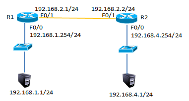
图-1
1.3 步骤
实现此案例需要按照如下步骤进行。
步骤一:配置静态路由
1)R1上配置接口IP
- R1(config)#interface fastEthernet 0/0
- R1(config-if)#ip address 192.168.1.254 255.255.255.0
- R1(config-if)#no shutdown
- R1(config-if)#exit
- R1(config)#interface fastEthernet 0/1
- R1(config-if)#ip address 192.168.2.1 255.255.255.0
- R1(config-if)#no shutdown
2)R2上配置接口IP
- R2(config)#interface fastEthernet 0/1
- R2(config-if)#ip address 192.168.2.2 255.255.255.0
- R2(config-if)#no shutdown
- R2config-if)#exit
- R2(config)#interface fastEthernet 0/0
- R2(config-if)#ip address 192.168.4.254 255.255.255.0
- R2(config-if)#no shutdown
3)R1上添加静态路由
- R1(config)#ip route 192.168.4.0 255.255.255.0 192.168.2.2
4)R1上查看路由表
- R1#show ip route
- Codes: C - connected, S - static, I - IGRP, R - RIP, M - mobile, B - BGP
- D - EIGRP, EX - EIGRP external, O - OSPF, IA - OSPF inter area
- N1 - OSPF NSSA external type 1, N2 - OSPF NSSA external type 2
- E1 - OSPF external type 1, E2 - OSPF external type 2, E - EGP
- i - IS-IS, L1 - IS-IS level-1, L2 - IS-IS level-2, ia - IS-IS inter area
- * - candidate default, U - per-user static route, o - ODR
- P - periodic downloaded static route
- Gateway of last resort is not set
- C 192.168.1.0/24 is directly connected, FastEthernet0/0
- C 192.168.2.0/24 is directly connected, FastEthernet0/1
- S 192.168.4.0/24 [1/0] via 192.168.2.2 //S表示静态路由
5)R2上添加静态路由
- R2(config)#ip route 192.168.1.0 255.255.255.0 192.168.2.1
6)R2上查看路由条目
- R2#show ip route
- Codes: C - connected, S - static, I - IGRP, R - RIP, M - mobile, B - BGP
- D - EIGRP, EX - EIGRP external, O - OSPF, IA - OSPF inter area
- N1 - OSPF NSSA external type 1, N2 - OSPF NSSA external type 2
- E1 - OSPF external type 1, E2 - OSPF external type 2, E - EGP
- i - IS-IS, L1 - IS-IS level-1, L2 - IS-IS level-2, ia - IS-IS inter area
- * - candidate default, U - per-user static route, o - ODR
- P - periodic downloaded static route
- Gateway of last resort is not set
- S 192.168.1.0/24 [1/0] via 192.168.2.1 //S表示静态路由
- C 192.168.2.0/24 is directly connected, FastEthernet0/1
- C 192.168.3.0/24 is directly connected, FastEthernet0/0
7)配置PC1的IP地址为192.168.1.1,网关为192.168.1.254
8)配置PC2的IP地址为192.168.4.1,网关为192.168.4.254
9)测试网络连通性,PC1 ping 192.168.4.1
- PC>ping 192.168.4.1
- Pinging 192.168.4.1 with 32 bytes of data:
- Reply from 192.168.4.1: bytes=32 time=1ms TTL=126
- Reply from 192.168.4.1: bytes=32 time=11ms TTL=126
- Reply from 192.168.4.1: bytes=32 time=10ms TTL=126
- Reply from 192.168.4.1: bytes=32 time=11ms TTL=126
- Ping statistics for 192.168.4.1:
- Packets: Sent = 4, Received = 4, Lost = 0 (0% loss),
- Approximate round trip times in milli-seconds:
- Minimum = 1ms, Maximum = 11ms, Average = 8ms
2 案例2:配置浮动路由
2.1 问题
配置浮动静态路由
2.2 方案
按如下网络拓扑配置接口IP地址配置浮动路由实现链路的冗余,如图-2所示
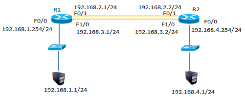
图-2
2.3 步骤
实现此案例需要按照如下步骤进行。
步骤一:配置静态路由并添加模块
1)R1上配置接口IP
在以上静态路由实验的基础上,先分别进入R1与R2的特权模式输入write命令保存配置信息,然后分别进入R1与R2的物理配置界面,点击开关按钮关闭路由器,添加NM-1FE-TX模块并再次点击开关按钮,如下图-3所示。
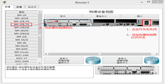
图-3
2)添加模块后将R1的F1/0接口连接到R2的F1/0接口修改拓扑如下图-4所示:
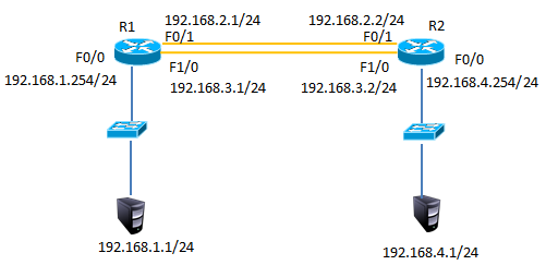
图-4
3)配置R1的F1/0接口IP
- R1(config)#interface fastEthernet 1/0
- R1(config-if)#ip address 192.168.3.1 255.255.255.0
- R1(config-if)#no shutdown
4)配置R2的F1/0接口IP
- R2(config)#interface fastEthernet 1/0
- R2(config-if)#ip address 192.168.3.2 255.255.255.0
- R2(config-if)#no shutdown
5)R1上添加静态浮动路由
- R1(config)#ip route 192.168.4.0 255.255.255.0 192.168.3.2 50 //管理距离50
6)R2上添加静态浮动路由
- R2(config)#ip route 192.168.1.0 255.255.255.0 192.168.3.1 50 //管理距离50
7)R1上查看路由表
- R1#show ip route
- Codes: C - connected, S - static, I - IGRP, R - RIP, M - mobile, B - BGP
- D - EIGRP, EX - EIGRP external, O - OSPF, IA - OSPF inter area
- N1 - OSPF NSSA external type 1, N2 - OSPF NSSA external type 2
- E1 - OSPF external type 1, E2 - OSPF external type 2, E - EGP
- i - IS-IS, L1 - IS-IS level-1, L2 - IS-IS level-2, ia - IS-IS inter area
- * - candidate default, U - per-user static route, o - ODR
- P - periodic downloaded static route
- Gateway of last resort is not set
- C 192.168.1.0/24 is directly connected, FastEthernet0/0
- C 192.168.2.0/24 is directly connected, FastEthernet0/1
- C 192.168.3.0/24 is directly connected, FastEthernet1/0
- S 192.168.4.0/24 [1/0] via 192.168.2.2 //只有下一跳为192.168.2.2的静态路由
8)禁用F/01接口
- R1(config)#interface fastEthernet 0/1
- R1(config-if)#shutdown
9)R1上查看路由表
- C 192.168.1.0/24 is directly connected, FastEthernet0/0
- S 192.168.4.0/24 [50/0] via 192.168.3.2//下一跳接口为192.168.4.2的路由生效
- C 192.168.4.0/24 is directly connected, FastEthernet1/0
10)测试网络连通性,PC1 ping 192.168.4.1
- PC>ping 192.168.4.1
- Pinging 192.168.4.1 with 32 bytes of data:
- Reply from 192.168.4.1: bytes=32 time=0ms TTL=126
- Reply from 192.168.4.1: bytes=32 time=10ms TTL=126
- Reply from 192.168.4.1: bytes=32 time=11ms TTL=126
- Reply from 192.168.4.1: bytes=32 time=1ms TTL=126
- Ping statistics for 192.168.4.1:
- Packets: Sent = 4, Received = 4, Lost = 0 (0% loss),
- Approximate round trip times in milli-seconds:
- Minimum = 0ms, Maximum = 11ms, Average = 5ms
3 案例3:配置多路由的静态路由
3.1 问题
配置多路由的静态路由
3.2 方案
网络环境及IP地址规划,如图-5所示
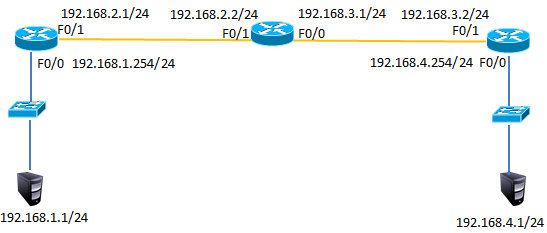
图-5
3.3 步骤
实现此案例需要按照如下步骤进行。
步骤一:配置路由IP和静态路由
1) R1上配置接口IP
- Router(config)#interface fastEthernet 0/0
- R1(config-if)#ip address 192.168.1.254 255.255.255.0
- R1(config-if)#no shutdown
- R1(config-if)#exit
- R1(config)#interface fastEthernet 0/1
- R1(config-if)#ip address 192.168.2.1 255.255.255.0
- R1(config-if)#no shutdown
2)R2上配置接口IP
- R2(config)#interface f0/1
- R2(config-if)#ip address 192.168.2.2 255.255.255.0
- R2(config-if)#no shutdown
- R2(config-if)#exit
- R2(config)#interface fastEthernet 0/0
- R2(config-if)#ip address 192.168.3.1 255.255.255.0
- R2(config-if)#no shutdown
3)R3上配置接口IP
- R3(config)#interface fastEthernet 0/1
- R3(config-if)#ip address 192.168.3.2 255.255.255.0
- R3(config-if)#no shutdown
- R3(config-if)#exit
- R3(config)#interface fastEthernet 0/0
- R3(config-if)#ip address 192.168.4.254 255.255.255.0
- R3(config-if)#no shutdown
4)R1、R2、R3上分别添加静态路由
- R1(config)#ip route 192.168.3.0 255.255.255.0 192.168.2.2
- R1(config)#ip route 192.168.4.0 255.255.255.0 192.168.2.2
- R2(config)#ip route 192.168.1.0 255.255.255.0 192.168.2.1
- R2(config)#ip route 192.168.4.0 255.255.255.0 192.168.3.2
- R3(config)#ip route 192.168.1.0 255.255.255.0 192.168.3.1
- R3(config)#ip route 192.168.2.0 255.255.255.0 192.168.3.1
5)R1上查看路由表
- R1#show ip route
- Codes: C - connected, S - static, I - IGRP, R - RIP, M - mobile, B - BGP
- D - EIGRP, EX - EIGRP external, O - OSPF, IA - OSPF inter area
- N1 - OSPF NSSA external type 1, N2 - OSPF NSSA external type 2
- E1 - OSPF external type 1, E2 - OSPF external type 2, E - EGP
- i - IS-IS, L1 - IS-IS level-1, L2 - IS-IS level-2, ia - IS-IS inter area
- * - candidate default, U - per-user static route, o - ODR
- P - periodic downloaded static route
- Gateway of last resort is not set
- C 192.168.1.0/24 is directly connected, FastEthernet0/0
- C 192.168.2.0/24 is directly connected, FastEthernet0/1
- S 192.168.3.0/24 [1/0] via 192.168.2.2 //静态路由
- S 192.168.4.0/24 [1/0] via 192.168.2.2 //静态路由
6)R2上查看路由表
- R2#show ip route
- Codes: C - connected, S - static, I - IGRP, R - RIP, M - mobile, B - BGP
- D - EIGRP, EX - EIGRP external, O - OSPF, IA - OSPF inter area
- N1 - OSPF NSSA external type 1, N2 - OSPF NSSA external type 2
- E1 - OSPF external type 1, E2 - OSPF external type 2, E - EGP
- i - IS-IS, L1 - IS-IS level-1, L2 - IS-IS level-2, ia - IS-IS inter area
- * - candidate default, U - per-user static route, o - ODR
- P - periodic downloaded static route
- Gateway of last resort is not set
- S 192.168.1.0/24 [1/0] via 192.168.2.1 //静态路由
- C 192.168.2.0/24 is directly connected, FastEthernet0/1
- C 192.168.3.0/24 is directly connected, FastEthernet0/0
- S 192.168.4.0/24 [1/0] via 192.168.3.2 //静态路由
7)R3上查看路由表
- R3#show ip route
- Codes: C - connected, S - static, I - IGRP, R - RIP, M - mobile, B - BGP
- D - EIGRP, EX - EIGRP external, O - OSPF, IA - OSPF inter area
- N1 - OSPF NSSA external type 1, N2 - OSPF NSSA external type 2
- E1 - OSPF external type 1, E2 - OSPF external type 2, E - EGP
- i - IS-IS, L1 - IS-IS level-1, L2 - IS-IS level-2, ia - IS-IS inter area
- * - candidate default, U - per-user static route, o - ODR
- P - periodic downloaded static route
- Gateway of last resort is not set
- S 192.168.1.0/24 [1/0] via 192.168.3.1 //静态路由
- S 192.168.2.0/24 [1/0] via 192.168.3.1 //静态路由
- C 192.168.3.0/24 is directly connected, FastEthernet0/1
- C 192.168.4.0/24 is directly connected, FastEthernet0/0
8)按图-4配置PC的IP地址
9)测试网络连通性,PC1 ping 192.168.2.2、192.168.3.1、192.168.3.2、192.168.4.1
- PC>ping 192.168.2.2 //ping 192.168.2.2
- Pinging 192.168.2.2 with 32 bytes of data:
- Reply from 192.168.2.2: bytes=32 time=0ms TTL=254
- Reply from 192.168.2.2: bytes=32 time=0ms TTL=254
- Reply from 192.168.2.2: bytes=32 time=0ms TTL=254
- Reply from 192.168.2.2: bytes=32 time=0ms TTL=254
- Ping statistics for 192.168.2.2:
- Packets: Sent = 4, Received = 4, Lost = 0 (0% loss),
- Approximate round trip times in milli-seconds:
- Minimum = 0ms, Maximum = 0ms, Average = 0ms
- PC>ping 192.168.3.1 //ping 192.168.3.1
- Pinging 192.168.3.1 with 32 bytes of data:
- Reply from 192.168.3.1: bytes=32 time=0ms TTL=254
- Reply from 192.168.3.1: bytes=32 time=3ms TTL=254
- Reply from 192.168.3.1: bytes=32 time=0ms TTL=254
- Reply from 192.168.3.1: bytes=32 time=0ms TTL=254
- Ping statistics for 192.168.3.1:
- Packets: Sent = 4, Received = 4, Lost = 0 (0% loss),
- Approximate round trip times in milli-seconds:
- Minimum = 0ms, Maximum = 3ms, Average = 0ms
- PC>ping 192.168.3.2 //ping 192.168.3.2
- Pinging 192.168.3.2 with 32 bytes of data:
- Reply from 192.168.3.2: bytes=32 time=0ms TTL=253
- Reply from 192.168.3.2: bytes=32 time=12ms TTL=253
- Reply from 192.168.3.2: bytes=32 time=0ms TTL=253
- Reply from 192.168.3.2: bytes=32 time=12ms TTL=253
- Ping statistics for 192.168.3.2:
- Packets: Sent = 4, Received = 4, Lost = 0 (0% loss),
- Approximate round trip times in milli-seconds:
- Minimum = 0ms, Maximum = 12ms, Average = 6ms
- PC>ping 192.168.4.1 //ping 192.168.4.1
- Pinging 192.168.4.1 with 32 bytes of data:
- Reply from 192.168.4.1: bytes=32 time=0ms TTL=125
- Reply from 192.168.4.1: bytes=32 time=10ms TTL=125
- Reply from 192.168.4.1: bytes=32 time=0ms TTL=125
- Reply from 192.168.4.1: bytes=32 time=22ms TTL=125
- Ping statistics for 192.168.4.1:
- Packets: Sent = 4, Received = 4, Lost = 0 (0% loss),
- Approximate round trip times in milli-seconds:
- Minimum = 0ms, Maximum = 22ms, Average = 8ms
4 案例4:配置默认路由
4.1 问题
配置默认路由
4.2 方案
网络环境及IP地址规划,如图-6所示

图-6
4.3 步骤
1)在案例3基础上删除R1与R3的静态路由
- R1(config)#no ip route 192.168.3.0 255.255.255.0 192.168.2.2
- R1(config)#no ip route 192.168.4.0 255.255.255.0 192.168.2.2
- R3(config)#no ip route 192.168.1.0 255.255.255.0 192.168.3.1
- R3(config)#no ip route 192.168.2.0 255.255.255.0 192.168.3.1
2)R1、R3添加默认路由
- R1(config)#ip route 0.0.0.0 0.0.0.0 192.168.2.2
- R3(config)#ip route 0.0.0.0 0.0.0.0 192.168.3.1
- 12)R1上查看路由表
- R1#show ip route
- Codes: C - connected, S - static, I - IGRP, R - RIP, M - mobile, B - BGP
- D - EIGRP, EX - EIGRP external, O - OSPF, IA - OSPF inter area
- N1 - OSPF NSSA external type 1, N2 - OSPF NSSA external type 2
- E1 - OSPF external type 1, E2 - OSPF external type 2, E - EGP
- i - IS-IS, L1 - IS-IS level-1, L2 - IS-IS level-2, ia - IS-IS inter area
- * - candidate default, U - per-user static route, o - ODR
- P - periodic downloaded static route
- Gateway of last resort is 192.168.2.2 to network 0.0.0.0
- C 192.168.1.0/24 is directly connected, FastEthernet0/0
- C 192.168.2.0/24 is directly connected, FastEthernet0/1
- S* 0.0.0.0/0 [1/0] via 192.168.2.2 //默认路由
3)R1、R3上查看路由表
- R1#show ip route
- Codes: C - connected, S - static, I - IGRP, R - RIP, M - mobile, B - BGP
- D - EIGRP, EX - EIGRP external, O - OSPF, IA - OSPF inter area
- N1 - OSPF NSSA external type 1, N2 - OSPF NSSA external type 2
- E1 - OSPF external type 1, E2 - OSPF external type 2, E - EGP
- i - IS-IS, L1 - IS-IS level-1, L2 - IS-IS level-2, ia - IS-IS inter area
- * - candidate default, U - per-user static route, o - ODR
- P - periodic downloaded static route
- Gateway of last resort is 192.168.3.1 to network 0.0.0.0
- C 192.168.1.0/24 is directly connected, FastEthernet0/0
- C 192.168.2.0/24 is directly connected, FastEthernet0/1
- S* 0.0.0.0/0 [1/0] via 192.168.2.2 //默认路由
- R3#show ip route
- Codes: C - connected, S - static, I - IGRP, R - RIP, M - mobile, B - BGP
- D - EIGRP, EX - EIGRP external, O - OSPF, IA - OSPF inter area
- N1 - OSPF NSSA external type 1, N2 - OSPF NSSA external type 2
- E1 - OSPF external type 1, E2 - OSPF external type 2, E - EGP
- i - IS-IS, L1 - IS-IS level-1, L2 - IS-IS level-2, ia - IS-IS inter area
- * - candidate default, U - per-user static route, o - ODR
- P - periodic downloaded static route
- Gateway of last resort is 192.168.3.1 to network 0.0.0.0
- C 192.168.3.0/24 is directly connected, FastEthernet0/1
- C 192.168.4.0/24 is directly connected, FastEthernet0/0
- S* 0.0.0.0/0 [1/0] via 192.168.3.1 //默认路由
4)测试网络连通性,PC1 ping 192.168.4.1
- PC>ping 192.168.4.1
- Pinging 192.168.4.1 with 32 bytes of data:
- Reply from 192.168.4.1: bytes=32 time=1ms TTL=125
- Reply from 192.168.4.1: bytes=32 time=0ms TTL=125
- Reply from 192.168.4.1: bytes=32 time=14ms TTL=125
- Reply from 192.168.4.1: bytes=32 time=14ms TTL=125
- Ping statistics for 192.168.4.1:
- Packets: Sent = 4, Received = 4, Lost = 0 (0% loss),
- Approximate round trip times in milli-seconds:
- Minimum = 0ms, Maximum = 14ms, Average = 7ms = 0ms,平均 = 0ms