下面是根据书上103页,图4.4(e),分别采用8-连通和4-连通两种方式进行边界追迹的简单示例程序:
void traceEdge(Mat&img,int neighbor=1)
{
    Mat tempImg=img.clone();
    cv::cvtColor(tempImg,tempImg,CV_BGR2GRAY);
    for(int i=1;i<img.rows;i++)
    {
        for(int j=1;j<img.cols;j++)
        {
            uchar v=tempImg.ptr<uchar>(i)[j];

            if(v>0)
            {
                uchar p1=tempImg.ptr<uchar>(i-1)[j-1];
                uchar p2=tempImg.ptr<uchar>(i-1)[j];
                uchar p3=tempImg.ptr<uchar>(i-1)[j+1];

                uchar p4=tempImg.ptr<uchar>(i)[j-1];
                uchar p5=tempImg.ptr<uchar>(i)[j+1];

                uchar p6=tempImg.ptr<uchar>(i+1)[j-1];
                uchar p7=tempImg.ptr<uchar>(i+1)[j];
                uchar p8=tempImg.ptr<uchar>(i+1)[j+1];
                switch(neighbor)
                {
                case 0:
                    if(p2*p4*p5*p7==0)
                        img.ptr<Vec3b>(i)[j]=Vec3b(0,0,255);
                    break;
                case 1:
                    if(p1*p2*p3*p4*p5*p6*p7*p8==0)
                        img.ptr<Vec3b>(i)[j]=Vec3b(0,0,255);
                    break;
                }


            }
        }
    }
}

int main()
{
    Mat img(500,500,CV_8UC3,Scalar::all(0));
    Point vertices1[6]={Point(30,30),Point(130,30),Point(130,100),
                        Point(160,100),Point(160,230),Point(30,230)};
    const Point *pts[2]={vertices1};
    int npts[]={6};
    int ncontour=1;
    cv::fillPoly(img,pts,npts,ncontour,Scalar(255,255,0));
    imshow("fillPoly image",img);
    waitKey();

    traceEdge(img,0);
    imshow("trae Edge image",img);
    waitKey();
    return 0;
}
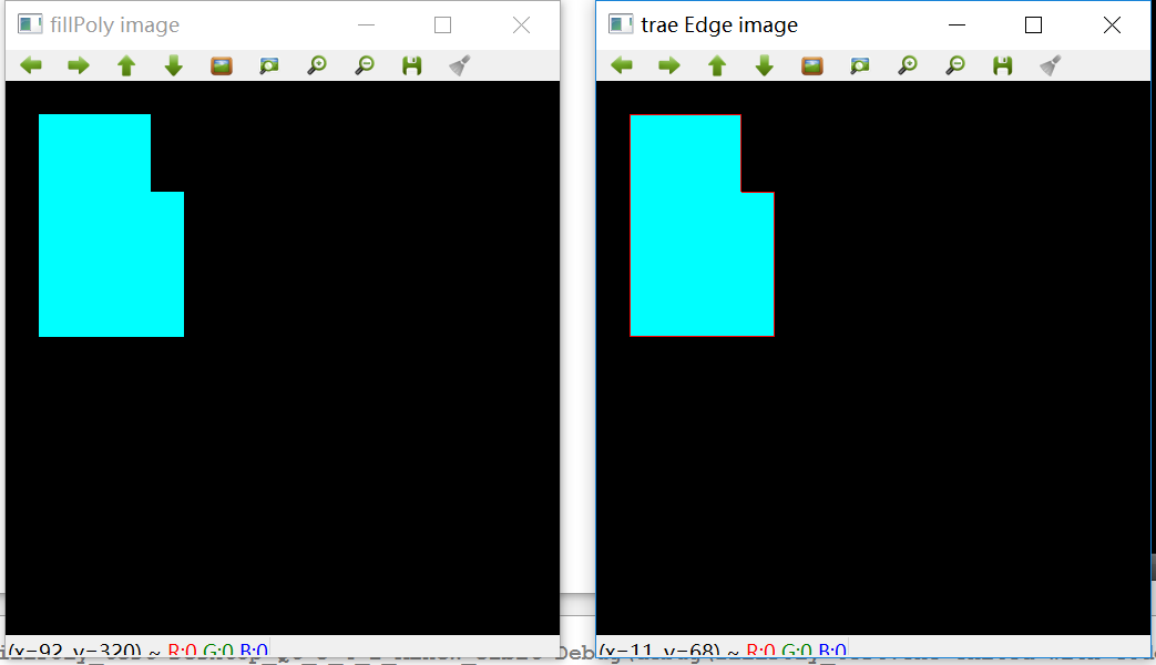
运行结果如下,左图是一个多边形图像,背景为黑色。右图是采用4-连通的方式追迹边界的结果
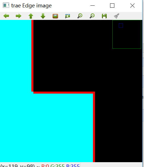
为了看得清楚,将上图拐角处放到如下,从图中我们可以看到,拐角处是不连续的边线。
接下来,我们再看看8-连通边缘追迹结果:
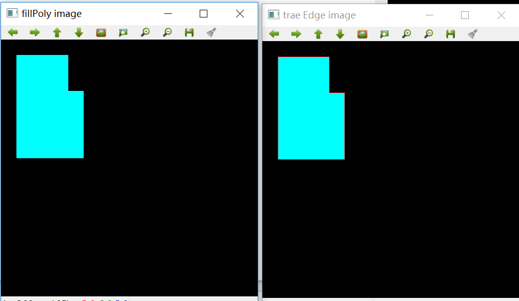
上面左图是原图,右图是8-连通追迹的结果,为了看清楚效果,将上面的右图拐角处放大如下,从图中我们看到拐角处是连续的红色边线。
