状态机设计分析
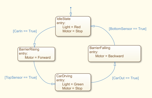
根据要求,可以分为四个状态,令起落杆上限位传感器为TopSensor,下限位传感器为BottomSensor,汽车入闸传感器为CarIn,汽车出闸传感器为CarOut,则有
- S1:Idle
- 进入时设置通行灯为红灯,电机停止。
- 当汽车入闸传感器CarIn变为True时,转移到状态S2
- S2: BarrierRising
- 进入时设置电机正转,保持通行灯状态
- 当上限位传感器TopSensor变为True时,转移到状态S3
- S3: CarDriving
- 进入时设置通行灯为绿灯,电机停止
- 当汽车出闸传感器CarOut变为True时,转移到状态S4
- S4:BarrierFalling
- 进入时设置电机反转,保持通行灯状态
- 当下限位传感器BottomSensor变为True时,转移到状态S1
根据以上设计,建立模型。
MATLAB/Simulink Stateflow 模拟运行
状态机建模
运行示例
模型文件
C++ 实现
以Simulink Stateflow的模块为模板,作出以下设计。
状态机抽象
首先,设计三个类:一个用于表示状态,可以通过一个函数,检查绑定的触发条件,并返回符合条件的下一状态。类声明如下:
class State {
public:
    std::string Name;
    State(std::string);
    State* Trigger(void);
    void Add(std::function<bool(void)> fn, State* NextState);
    void SetEntry(void(*fn)(void));
    void Entry(void);

private:
    std::vector<std::function<bool(void)>> Condition;
    std::vector<State*> NextState;
    void (*FnEntry)(void);
};

class Machine {
public:
    Machine(State *InitState);
    void SetState(State *state);
    State *Curr;
    void Trigger(void);
};
一个类为布尔型传感器类,继承于传感器类模版。声明分别为:
template <typename T>
class TSensor {
protected:
    T value;

public:
    TSensor(){}
    TSensor(T value) {
        this->Set(value);
    }
    void Set(T value) {
        this->value = value;
    }
    T Get(void) {
        return this->value;
    }
};

class BoolSensor: public TSensor<bool> {
public:
    BoolSensor(bool value);
    bool IsTrue(void);
    bool IsFalse(void);
};
另一个类则为模拟机,模拟触发状态检查,并维护状态机的当前状态,同时在改变状态时能够触发相应的进入操作。类声明如下:
class Machine {
public:
    Machine(State *InitState);
    void SetState(State *state);
    State *Curr;
    void Trigger(void);
};
组装模型
// 定义传感器
    // 测试模型时所有传感器默认值均设为true,正常情况应默认为false
    BoolSensor CarIn{true};
    BoolSensor CarOut{true};
    BoolSensor TopSensor{true};
    BoolSensor BottomSensor{true};

// 定义状态
    State S1{"Idle"};
    State S2{"Barrier Rising"};
    State S3{"Car Driving"};
    State S4{"Barrier Falling"};

// 设置状态转移及入口动作
    S1.SetEntry(&S1_Entry);
    S1.Add(std::bind(&BoolSensor::IsTrue, &CarIn), &S2);

    S2.SetEntry(&S2_Entry);
    S2.Add(std::bind(&BoolSensor::IsTrue, &TopSensor), &S3);

    S3.SetEntry(&S3_Entry);
    S3.Add(std::bind(&BoolSensor::IsTrue, &CarOut), &S4);

    S4.SetEntry(&S4_Entry);
    S4.Add(std::bind(&BoolSensor::IsTrue, &BottomSensor), &S1);
其中,SetEntry为设置状态机的进入状态时的触发动作。
初始化并模拟运行
初始状态为S1,即Idle状态。
    Machine simulate{&S1};

    while (1) {
        simulate.Trigger();
        sleep(1);
    }
运行效果
Set State <Idle>
Light: Red
Motor: Stop
Switch From <Idle> to <Barrier Rising>
Light: Red
Motor: Forward Revolute
Switch From <Barrier Rising> to <Car Driving>
Light: Green
Motor: Stop
Switch From <Car Driving> to <Barrier Falling>
Light: Green
Motor: Backward Revolute
Switch From <Barrier Falling> to <Idle>
Light: Red
Motor: Stop
...
源代码
References
[1] [https://cn.mathworks.com/help/stateflow/ug/programming-your-chart-with-matlab-syntax.html]