最近使用了一款Cortex-M0内核的芯片STM32F030CC,发现它中断向量表的重映射方法与STM32F10x系列的有所区别,在这里记录与分享一下。
由于需要通过IAP进行固件升级,所以芯片的FLASH里面要烧录两份代码:一个Boot loader, 一个用户应用程序。理所当然的,在用户应用程序中,必须得重新映射中断向量表。
可是在ST提供的固件库里,我却没有发现类似于stm32f10x固件库中的void NVIC_SetVectorTable(uint32_t NVIC_VectTab, uint32_t Offset)接口。
浏览了一下Cortex-M0的Programming manual,原来M0并没有SCB->VTOR这个寄存器,难怪ST的库里没有提供NVIC_SetVectorTable这个接口。
这下要怎么办?在网络上搜索了一下,受到网友findaway123这篇文章的启发,我在STM32F030CC的Reference manual中找到以下说明:
Physical remap
Once the boot mode is selected, the application software can modify the memory accessible in the code area.This modification is performed by programming the MEM_MODE bits in the SYSCFG configuration register 1 (SYSCFG_CFGR1). Unlike Cortex® M3 and M4, the M0 CPU does not support the vector table relocation. For application code which is located in a different address than 0x0800 0000, some additional code must be added in order to be able to serve the application interrupts. A solution will be to relocate by software the vector table to the internal SRAM:
• Copy the vector table from the Flash (mapped at the base of the application load address) to the base address of the SRAM at 0x2000 0000.
• Remap SRAM at address 0x0000 0000, using SYSCFG configuration register 1.
• Then once an interrupt occurs, the Cortex®-M0 processor will fetch the interrupt handler start address from the relocated vector table in SRAM, then it will jump to execute the interrupt handler located in the Flash.
This operation should be done at the initialization phase of the application. Please refer to AN4065 and attached IAP code from www.st.com for more details.
OK,解决方法找到了!
在用户应用程序中,按照以上方法,添加以下两行代码:
    memcpy((void*)0x20000000, (void*)0x08004000, VECTOR_SIZE);
    SYSCFG_MemoryRemapConfig(SYSCFG_MemoryRemap_SRAM);
其中,0x2000 0000是SRAM的起始地址,这个不需要改动。
而之后的两个参数需要根据实际情况作出修改。0x0800 4000是应用程序的起址地址,从这里开始的VECTOR_SIZE字节,存放是的应用程序的中断向量表。VECTOR_SIZE是指中断向量表的大小,具体多大可以在startup.s文件里计算得到。以下以startup_stm32f030.s为例作说明:
  1 Stack_Size      EQU     0x00000400
  2
  3                 AREA    STACK, NOINIT, READWRITE, ALIGN=3
  4 Stack_Mem       SPACE   Stack_Size
  5 __initial_sp
  6
  7
  8 ; <h> Heap Configuration
  9 ;   <o>  Heap Size (in Bytes) <0x0-0xFFFFFFFF:8>
 10 ; </h>
 11
 12 Heap_Size       EQU     0x00000200
 13
 14                 AREA    HEAP, NOINIT, READWRITE, ALIGN=3
 15 __heap_base
 16 Heap_Mem        SPACE   Heap_Size
 17 __heap_limit
 18
 19                 PRESERVE8
 20                 THUMB
 21
 22
 23 ; Vector Table Mapped to Address 0 at Reset
 24                 AREA    RESET, DATA, READONLY
 25                 EXPORT  __Vectors
 26                 EXPORT  __Vectors_End
 27                 EXPORT  __Vectors_Size
 28
 29 __Vectors       DCD     __initial_sp                   ; Top of Stack
 30                 DCD     Reset_Handler                  ; Reset Handler
 31                 DCD     NMI_Handler                    ; NMI Handler
 32                 DCD     HardFault_Handler              ; Hard Fault Handler
 33                 DCD     0                              ; Reserved
 34                 DCD     0                              ; Reserved
 35                 DCD     0                              ; Reserved
 36                 DCD     0                              ; Reserved
 37                 DCD     0                              ; Reserved
 38                 DCD     0                              ; Reserved
 39                 DCD     0                              ; Reserved
 40                 DCD     SVC_Handler                    ; SVCall Handler
 41                 DCD     0                              ; Reserved
 42                 DCD     0                              ; Reserved
 43                 DCD     PendSV_Handler                 ; PendSV Handler
 44                 DCD     SysTick_Handler                ; SysTick Handler
 45
 46                 ; External Interrupts
 47                 DCD     WWDG_IRQHandler                ; Window Watchdog
 48                 DCD     0                              ; Reserved
 49                 DCD     RTC_IRQHandler                 ; RTC through EXTI Line
 50                 DCD     FLASH_IRQHandler               ; FLASH
 51                 DCD     RCC_IRQHandler                 ; RCC
 52                 DCD     EXTI0_1_IRQHandler             ; EXTI Line 0 and 1
 53                 DCD     EXTI2_3_IRQHandler             ; EXTI Line 2 and 3
 54                 DCD     EXTI4_15_IRQHandler            ; EXTI Line 4 to 15
 55                 DCD     0                              ; Reserved
 56                 DCD     DMA1_Channel1_IRQHandler       ; DMA1 Channel 1
 57                 DCD     DMA1_Channel2_3_IRQHandler     ; DMA1 Channel 2 and Channel 3
 58                 DCD     DMA1_Channel4_5_IRQHandler     ; DMA1 Channel 4 and Channel 5
 59                 DCD     ADC1_IRQHandler                ; ADC1
 60                 DCD     TIM1_BRK_UP_TRG_COM_IRQHandler ; TIM1 Break, Update, Trigger and Commutation
 61                 DCD     TIM1_CC_IRQHandler             ; TIM1 Capture Compare
 62                 DCD     0                              ; Reserved
 63                 DCD     TIM3_IRQHandler                ; TIM3
 64                 DCD     0                              ; Reserved
 65                 DCD     0                              ; Reserved
 66                 DCD     TIM14_IRQHandler               ; TIM14
 67                 DCD     TIM15_IRQHandler               ; TIM15
 68                 DCD     TIM16_IRQHandler               ; TIM16
 69                 DCD     TIM17_IRQHandler               ; TIM17
 70                 DCD     I2C1_IRQHandler                ; I2C1
 71                 DCD     I2C2_IRQHandler                ; I2C2
 72                 DCD     SPI1_IRQHandler                ; SPI1
 73                 DCD     SPI2_IRQHandler                ; SPI2
 74                 DCD     USART1_IRQHandler              ; USART1
 75                 DCD     USART2_IRQHandler              ; USART2
 76
 77 __Vectors_End
 78
 79 __Vectors_Size  EQU  __Vectors_End - __Vectors
 80
 81                 AREA    |.text|, CODE, READONLY
 82
 83 ; Reset handler routine
 84 Reset_Handler    PROC
 85                  EXPORT  Reset_Handler                 [WEAK]
 86         IMPORT  __main
 87         IMPORT  SystemInit
 88
 89
 90
 91         LDR     R0, =__initial_sp          ; set stack pointer
 92         MSR     MSP, R0
 93
我们只需关注其中的一小部分。从29行开始,直到75行,每一个DCD都代表一个中断向量(所谓中断向量,说得明白点,其实就是某个中断服务程序的入口地址)。例如第74行的:
DCD USART1_IRQHandler ; USART1
这里的“USART1_IRQHandler"其实就是UART1中断服务程序USART1_IRQHandler这个函数,同时,它也代表这个函数的入口地址。
以上代码即定义了这样一张表,这张表包括45个元素,每个元素是一个长度为4字节的地址。除了第一个地址是SP(堆栈指针)外,其它的地址都是某个中断服务程序的入口地址。
那么,回到我们要解决的问题上来,之前memcpy函数中的第三个参数VECTOR_SIZE,针对本例,就应该是45*4=180(0xB4)个字节。
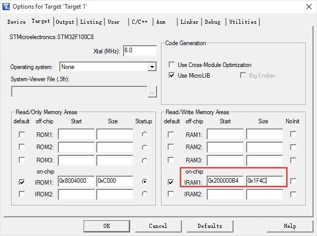
在执行完以上两行代码后,若发生中断,CPU就会去SRAM(即0x2000 0000处)取中断向量了,所以,以0x2000 0000作为起始地址之后的VECTOR_SIZE个字节就不能被改动了。为了达到这VECTOR_SIZE个字节不被修改的目的,如下两种方法可以实现。
•在工程文件内修改SRAM的起始地址及长度,如下图
•如果使用了分散加载文件,则在分散加载文件中修改SRAM的起始地址及长度也能达到目的。
至此,STM32F0系列Cortex-M0内核芯片中断向量表重映射的问题已解决。