http://www.linkedin.com/pulse/using-raycasts-dynamically-generated-geometry-create-line-thomas
On this article, I'd like to propose an implementation of a Line of Sight, those that you'd see on old Commandos games (see picture above).
This approach will use raycasts to provide scenario detection and dynamically generated geometry to create a visual representation of it.
This kind of system is useful to, of course, provide the accurate view of a character, given an aperture angle, a sight distance and a number of iterations (i.e. rays to be launched).
Our initial system will be targeting functionality over performance, but on this same article I'll write about some optimization tips.
Raycasting
Orienting our rays correctly and working with the aperture angle
The aperture angle means the left-most ray's direction will be -apertureAngle/2 degrees from the character's transform.forward vector and the right-most, +apertureAngle/2 degrees. Also, every ray we cast will depart from the character's position. Note that we can have control over the magnitude of the resulting vector, therefore creating a sightDistance(how far can the character see) effect. The picture below tries to illustrate this idea more clearly.

This kind of behaviour can be achieved with the Quaternion.AngleAxis (float degrees, Vector3 axis) function, which rotates degrees around axis. You then multiply the resulting Quaternion by the vector you want to rotate, in this case transform.forward. The result is the transform.forward vector rotated degrees around axis. A working code (given that angleAperture is a defined variable) would be:
Vector3 rotatedVector = Quaternion.AngleAxis (-apertureAngle/2, Vector3.up) * transform.forward:
The axis you pass in as a parameter (Vector3.up) most likely will be orthogonal to the one you want to rotate (transform.forward).
Our raycasting algorithm will work like so:
- Cast a ray towards the current desired direction with a maximum distance of sightDistance. If we catch something in between, the final vector will be the direction * distance to the hit point. If not, the final vector is the direction * sightDistance.
- For each new final point (character's position + final vector) we have in the system, we create a new triangle to generate geometry, though we'll explore this later.
Click above to see the raycasting animation.
The number of lines in the image above is basically the number of iterations we set and setting this value correctly will play a huge role when generating geometry.
Geometry
Using the rays to generate a dynamic mesh
Generating dynamic geometry is extremely powerful though kind of tricky to get right and master. There are a few specific points we have to pay attention to:
- Vertices are an array of Vector3 (positions);
- Triangles are an array of int. The integers represent the indices of the array of vertices, so the mesh knows which vertices compose which triangle;
- The 3 vertices of each triangle need to be passed in counter-clock wise order, so the normal of the face gets calculated correctly, pointing out of the geometry;
- If you set up vertices and triangles and no geometry is displayed, it might be the order you passed the vertex indices, making the normals to be pointing inwards;
- The structure that holds geometry data is Mesh.
Something that makes live easier in this case is that the position of the character is always a vertex of a triangle, so each triangle is composed by the index 0, the current index and the one that came before.
Below you can see an example of how to generate mesh in Unity. The vertices are represented just by their index, starting at 0.
Click above to see the mesh generation workflow animation.

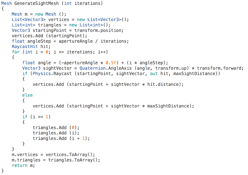
Here's the code that returns the Mesh structure with data correspondent to the generated geometry.

Click above to see the function workflow.

Note how iterations directly control the "resolution" of the geometry.
The function is pretty simple. First, we start by allocation memory space for the Lists that will keep the vertex and triangle data. We also define an angleStep, that is the amount of degrees that must be added each time in order to reach apertureAngle after iterations.
At each iteration we define the currentAngle (note how it starts at -apertureAngle * 0.5). We then cast a ray towards the desired direction. If we hit something, the hit position (i.e. startingPoint + sightVector * hit.distance) is the new vertex position, if not the vertex is placed at startingPoint + sightVector * maxSightDistance.
We start to define triangles after the second iteration (i >= 1) to make sure we have at least 3 vertices (the character's position and the first two). Also, note how vertex of index 0 (the character position) is always present in each triangle.
Optimization tip: instead of defining Lists every single time, we can allocate arrays with fixed size, because it is already known. We will always have iterations + 1 vertices (the extra one is for the character's position), so that's the vertex array size. Also, we'll have iterationstriangles. Since each triangle is composed of 3 vertices, the triangles array size is iterations * 3.
Conclusion
Putting it all together
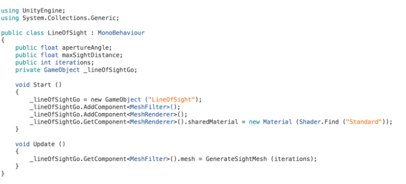
To get this to work, we just need to dynamically create a GameObject and attach the correct components to it, those that allow it to display geometry (MeshFilter and MeshRenderer). It's also important to give the MeshRenderer a Material just so we won't see that purple colour which bothers me, particularly speaking.
The position of the new GameObject doesn't have to be updated every frame because the mesh already takes into consideration the position of the character. Also, this script considers that it is attached to the Line of Sight's owner.
 Note how GenerateSightMesh is not declared here for simplicity purposes. Also, click on the image above to see the full plain-text code.
Optimization tip: instead of calling GenerateSightMesh every frame, we can call it in a coroutine and give it an update frequency, so every function called is delayed by 1/frequency.
You can attach a MeshCollider to this same GameObject and trigger events based on that, so you know exactly when something has entered the Line of Sight of your character. Another, more mathematical way of doing this would be to Dot product the transform.forward vector with the direction of your character pointing to the target (normalized). If that Dot product is less than the cosine of the apertureAngle and there are no obstacles between them and the distance is less than sightDistance, then the target is also in the character's view angle.
Well, I guess this is it for this article. I hope it was somehow useful to you! :)

5