Problem:
Is it possible to begin coding immediately after a requirements model has been created? Explain your answer and then argue the counterpoint.
Answer:
The analysis model will serve as a basis for the design and coding. It is possible to begin coding after objects, attributes; relationships are analyzed in analysis phase however the design will suffer as a result of explicit architecture design will not have been considered. Interfaces will have been developed in haphazard manner and global data structure will not have been explicitly designed.
Problem:
An analysis rule of thumb is that the model “should focus on requirements that are visible within the problem or business domain.” What types of requirements are not visible in these domains? Provide a few examples.
Answer:
Thumb rule of Analysis
• The model should focus on requirements which are visible with in problem or business domain.
• Abstraction levels are high in thumb rule
• New elements added in the analysis model should help in better understanding of the software requirements of the system.
• These elements provide better understanding of the functionality, behaviour and information domain of the system.
• Coupling should be minimized throughout the system
• The model should be simple
The following are the requirements not visible in these domains:
• Infrastructure requirements
o Functions required to manage global data
o Functions required to implement network communications
o Functions required to implement user interface
Problem:
What is the purpose of domain analysis? How is it related to the concept of requirements patterns?
Answer:
592-8-3P SA CODE: 4478
SR CODE: 4475
Domain analysis is an on-going software engineering activity that is not connected to any one software project
Purpose of domain analysis:
The key to reusable software is captured in domain analysis in that it stresses the reusability of analysis and design.
Domain analysis for requirement patterns
The requirement is to find analysis pattern that are widely used with in specific application domain and to identify a set of objects and classes that characterize the domain.
Problem:
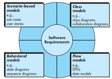
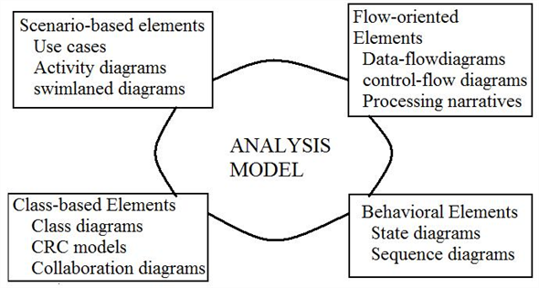
Is it possible to develop an effective analysis model without developing all four elements shown in Figure 9.3 ? Explain.
FIGURE 9.3 Elements of the analysis model
Answer:
It is possible to develop an effective analysis model without developing all four elements shown in Figure. The specific content of each element may differ from project to project.
However, each element presents a different view of the problem to be solved, and therefore provides the ability to see potential problems, inconsistencies or omissions more clearly. In addition, if all four elements of the analysis model are developed, the transition to design is simplified.
Problem:
The department of public works for a large city has decided to develop a Web-based pothole tracking and repair system (PHTRS). A description follows:
Citizens can log onto a website and report the location and severity of potholes. As potholes are reported they are logged within a “public works department repair system” and are assigned an identifying number, stored by street address, size (on a scale of 1 to 10), location (middle, curb, etc.), district (determined from street address), and repair priority (determined from the size of the pothole). Work order data are associated with each pothole and include pothole location and size, repair crew identifying number, number of people on crew, equipment assigned, hours applied to repair, hole status (work in progress, repaired, temporary repair, not repaired), amount of filler material used, and cost of repair (computed from hours applied, number of people, material and equipment used). Finally, a damage file is created to hold information about reported damage due to the pothole and includes citizen’s name, address, phone number, type of damage, and dollar amount of damage. PHTRS is an online system; all queries are to be made interactively.
Draw a UML use case diagram PHTRS system. You’ll have to make a number of assumptions about the manner in which a user interacts with this system.
Answer:
The department of public works for a city has decided to develop a web-based Pot Hole Tracking and Repair System (PHTRS). A UML use case diagram states the relationship between the actors in the system with the use cases.
To construct a unified modelling language (UML) use case diagram first identify the actors for the system. For PHTRS, actors can include:-
• Citizen
• PHTRS employees
• Contractor
• Repair Crew
Then, identify the functionalities to be identified as use case for the system. For PHTRS, functionalities can include:-
• Citizen reports pothole information like its severity and location.
• Record pothole information like identification number, size, location, address, repair priority in PHTRS.
• Issue work order with data like size, location, repair crew id number, crew size, equipment assigned, hours worked, status, cost or repair etc.
• Create a PHTRS damaged file with information like citizen name, phone number, and address, type of damage and cost of damage.
Now, construct a UML use case diagram for the PHTRS using above information
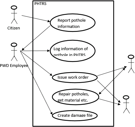
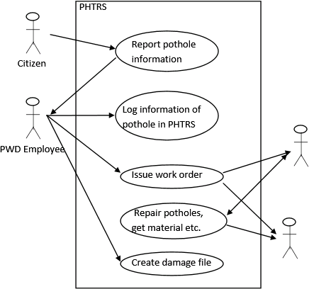
.
Figure 1: UML use case diagram for PHTRS.
Problem:
Write two or three use cases that describe the roles of various actors in the PHTRS described in Problem 9.5.
Answer:
The department of public works for a city has decided to develop a web-based Pot Hole Tracking and Repair System (PHTRS).
To construct use case for the system first identify the actors in the system. For PHTRS, actors can include:-
• Citizen
• PHTRS employees
• Contractor
• Repair Crew
Then, identify the functionalities to be identified as use case in the system. For PHTRS, functionalities can include:-
• Citizen reports pothole information like its severity and location.
• Log pothole information like identification number, size, location, address, repair priority in PHTRS.
• Issue work order with data like repair crew id number, repair crew size, equipment assigned, hours worked, status, cost or repair etc.
• Create a PHTRS damaged file with information such as citizen name, phone number, and address, type of damage and cost of damage.
Now, uses cases to describe the role of various actors can be:-
Use Case: Report Pothole
Primary Actor: Citizen
Goal in Context: To report a pothole along with any damage to citizen or property.
Precondition: Citizen is logged in a fully configured PHTRS.
Trigger: Citizen sees a pothole or faces loss due to the pothole, decides to report it.
Scenario:
1. The user clicks on 'Report Pothole' in the web site.
2. The web site displays a form to fill in following information: location on the street, severity, and address of Pothole.
3. The user fills his/her information into the fields, and if s/he faced damages.
4. The user Clicks on ‘Next’ button.
5. Site asks user for information about Type of damage done and cost if s/he choose damages in last section.
6. The user fills out all this information.
7. The user clicks on ‘Submit’ button.
8. The application stores all the information that Citizen entered in a database.
Open Issues:
1. Users can log bad data that would increase cost without any actual requirement.
2. Users can exaggerate damage.
3. No backup: In case the system goes down for any reason, records could be lost.
4. End-Users don't prefer to use the system.
Use Case: Create damage file
Primary Actor: PWD employee
Goal in Context: To create a damage file.
Precondition: The web based PHTRS is functional and a pothole has been repaired.
Trigger: Contractor informs PWD that the pothole has been repaired.
Scenario:
1. The PWD employee checks the quality and completeness of repair.
2. The PWD employee logs in the system with user id and password.
3. The application opens with an option to search an existing unrepaired pothole.
4. The PWD employee closes the status of just repaired pothole (repaired) and click on the ‘Create damage file’ button.
5. The application creates a damage file containing information of pothole and reporting damage caused to a citizen due to the pothole.
Open Issues:
1. The PWD employee might misjudge the quality of repair.
2. The contractor can exaggerate the cost of repair for more profit.
3. A contractor can misinform about quality of repair, wasting resources.
4. No backup: In case the system goes down for any reason, records could be lost.
5. PWD employees are reluctant to use the new system.
Problem:
Develop an activity diagram for one aspect of PHTRS.
Answer:
The department of public works for a city has decided to develop a web-based Pot Hole Tracking and Repair System (PHTRS).
One of the use case scenario for the system is:-
Use Case: Report Pothole
Primary Actor: Citizen
Goal in Context: To report a pothole with damage to citizen or property, if any.
Precondition: Citizen is logged in a fully configured web based PHTRS.
Trigger: Citizen sees a pothole or faces loss due to the pothole, decides to report it.
Scenario:
1. The user clicks on 'Report Pothole' in the web site.
2. The web site displays a form to fill in following information: location, severity, and address of Pothole.
3. The user fills his/her information into the fields, and if s/he needs to mention damages.
4. The user Clicks on ‘Next’ button.
5. Site asks user for information about Type of damage done and cost if s/he choose damages in last section.
6. The user fills out all this information.
7. The user clicks on ‘Submit’ button.
8. The application stores all the information that Citizen entered in a database.
The activity diagram in UML is a tool to provide a graphical representation of flow of interaction within a use case. Activity diagram are procedurally oriented. They resemble flowcharts.
The activity diagram for the ‘Report pothole’ use case can be:-
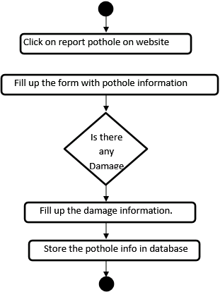
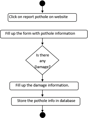
Figure 1: Activity diagram for ‘Report Pothole’ use case of PHTRS
Problem:
Develop a swimlane diagram for one or more aspects of PHTRS.
Answer:
The department of public works for a city has decided to develop a web-based Pot Hole Tracking and Repair System (PHTRS).
One of the use case scenario for the system is:-
Use Case: Report Pothole
Primary Actor: Citizen
Goal in Context: To report a pothole with damage to citizen or property, if any.
Precondition: Citizen is logged in a fully configured web based PHTRS.
Trigger: Citizen sees a pothole or faces loss due to the pothole, decides to report it.
Scenario:
1. The user clicks on 'Report Pothole' in the web site.
2. The web site displays a form to fill in following information: location on street, severity, and address of Pothole.
3. The user fills his/her information into the fields, and if s/he needs to mention damages.
4. The user Clicks on ‘Next’ button.
5. Site asks user for information about Type of damage done and cost if s/he choose damages in last section.
6. The user fills out all this information.
7. The user clicks on ‘Submit’ button.
8. The application stores all the information that Citizen entered in a database.
The UML swimlane diagram is an extension to activity diagram, which states the actors or analysis class responsible for an action. Swimlane diagram are procedure oriented.
In this use case, classes are Citizen and the web based application. So, the swimlane diagram for the above use case can look like:-
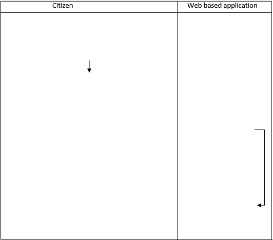
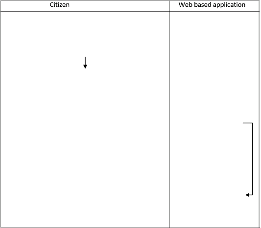
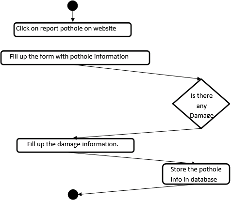
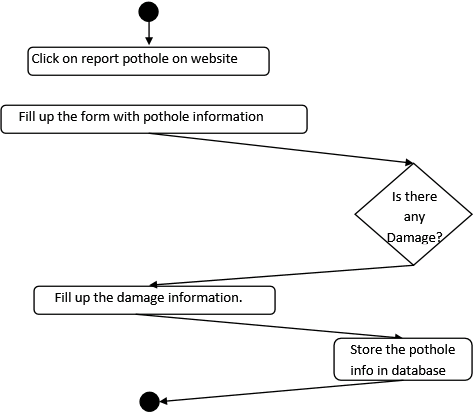
Figure 1: Swimlane diagram for ‘Report Pothole’ use case of PHTRS
As can be seen from Figure 1 above, the activity diagram of the ‘Report Pothole’ use case is spread out so that activities associated with an analysis class fall inside the swimlane for that class.
Solutions Chapter 9: REQUIREMENTS MODELING:SCENARIO-BASED
9.1) The analysis model will serve as the basis for design and construction of the domain objects. It is possible to begin coding after the objects and attributes are defined, and relationships are known.
9.2) As we know that complete specification of requirements may not be possible at the start stage. The customer may be unsure of precisely what is required. The developer may be unsure that a specific approach will properly accomplish function and performance. These realities mitigate in favor of an iterative approach to requirements analysis and modeling. The analyst should model what is known and use that model as the basis for design of the software increment that is produced as part of process iteration. The types of requirements are not visible in these domains may be what functions must the system perform, what behaviors does the system exhibit, what interfaces, are attributes defined, and what constraints apply?
9.3) Domain analysis is an ongoing software engineering activity that is not connected to any one software project. It is related to the concept of requirements patterns as domain analysis too is a process that can be characterized by a series of activities that begin with the identification of the domain to be investigated and end with a specification of the objects and classes that characterize the domain.
9.4) It is not possible to develop an effective analysis model without developing all four elements shown in Figure 6.3. The analysis model will serve as the basis for design and construction of the domain objects.
9.5) Answers will vary
9.6) Answers will vary
9.7) Answers will vary
9.8) Answers will vary