NetScaler VLAN’s Demystified
https://www.citrix.com/blogs/2014/12/29/netscaler-vlans-demystified/
The Citrix NetScaler appliance is an amazingly flexible application delivery controller (ADC). It’s capable of performing both simple and very complex tasks, positioning it solidly for the eighth consecutive year in the Gartner Leaders Quadrant for ADC’s: http://www.citrix.com/news/announcements/oct-2014/citrix-positioned-for-the-eighth-consecutive-year-in-the-leaders.html
Unlike many networking devices the NetScaler uses ‘floating’ IP addresses, which means that any NetScaler-owned IP address can egress any NetScaler interface with the generic default ‘vanilla’ configuration in place.
This may actually be the desired configuration, but if there is a need to ensure that ingress and egress traffic flows out one particular interface on the NetScaler, this can simply be configured by using layer three (L3) VLAN’s to bind IP subnets to specific interfaces. With L3 VLAN’s configured, all traffic destined for a particular network/subnet will be forced out the desired interface.
Note: VLAN’s are actually layer two constructs, but the term L3 VLAN is used to describe the VLAN-to-IP subnet binding occurring.
How Does This All Work?
By default all interfaces are members of Native VLAN 1. That being said, specific to RX and TX, there are a few different rules to understand.
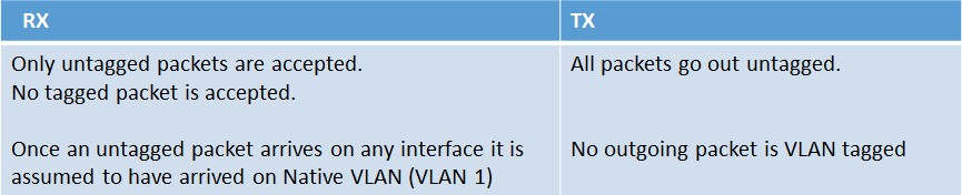
Below shows the structure of a VLAN packet:

Port-Based VLAN’s
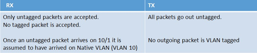
Let’s add a new VLAN to the NetScaler (VLAN 10). This new VLAN is created with the following command: ‘add vlan 10’
Then let’s bind interface 10/1 to the newly created VLAN 10 natively. This is accomplished with the following command: ‘bind vlan 10 -ifnum 10/1’
When bound natively, interface 10/1 is removed automatically from VLAN 1, the current native VLAN. It is then added to VLAN 10. When this configuration is implemented the following rules will then apply:
Tagged VLAN’s
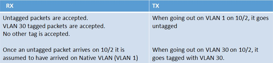
Let’s add a tagged VLAN to the NetScaler (VLAN 30). This new VLAN is created with the following command: ‘add vlan 30’
Then let’s bind interface 10/2 to the newly created VLAN 30 as a tagged member. This is accomplished with the following command: ‘bind vlan 30 -ifnum 10/2 –tagged’
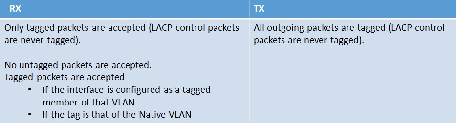
When VLAN 30 is bound as a tagged member of interface 10/2, it is kept in VLAN 1 as a native member, but also added to VLAN 30 as a tagged member. When this configuration is implemented the following rules will then apply.
Summary
- An interface can have only one (hence also referred to as ‘port based’) Native VLAN.
- Untagged packets arriving on an interface are assumed to have arrived on that Native VLAN.
- An interface can be part of any number of tagged VLANs.
- When an interface is bound to a VLAN Natively, its Native VLAN changes from the current one to new one.
- When an interface is bound to a particular VLAN as a tagged member, it’s just added to the new VLAN as a tagged member.
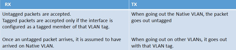
An overview of the rules are as follows:
The Interface TAGALL Configuration
The TAGALL configuration on the NetScaler is specific only to the interface. The following rules apply when leveraging the TAGALL feature:
Link Aggregation (LA)
Let’s create a new link aggregation channel. This new LA channel is created with the following command: ‘add channel LA/1’
Then let’s bind interfaces 10/1 and 10/2 to the newly created channel with the following command: ‘bind channel LA/1 -ifnum 10/1 10/2’
Then following rules will apply for the default LA channel:

Link Aggregation (LA) and VLANs
Let’s create a new link aggregation channel (LA/2). This new LA channel is created with the following command: ‘add channel LA/2’
Then let’s bind interfaces 10/1 and 10/2 to the newly created channel with the following command: bind channel LA/2 -ifnum 10/1 10/2’ (as referenced previously the VLAN bindings of 10/1 and 10/2 are lost once they are part of an LA channel – unless specifically configured as such as we’ll see in the following example).
We can bind the new LA channel to a new VLAN with the following commands: ‘add vlan 2’ and then ‘bind vlan 2 –ifnum LA/2’
NOTES:
- If we unbind interfaces 10/1 and 10/2 (for example) from an LA channel (e.g. ‘unbind channel LA/1 -ifnum 10/1 10/2’) and then remove the channel with the following command: ‘rm channel LA/1’, then interfaces 10/1 and 10/2 will be moved to VLAN 1 as Native members again.
- The NetScaler does not have the concept of “trunk ports”, which by default will accept all VLAN IDs and only accept tagged traffic. Further restrictions on which VLANs to accept can be controlled by configuring an ‘allowed list’ of VLAN IDs on a particular interface.
Additional References:
How to Associate an IP Subnet with a NetScaler Interface by Using VLANs:http://support.citrix.com/article/CTX136926
How to Restrict the Management Access to a NetScaler Appliance from a Specific Interface: http://support.citrix.com/article/CTX126038
-------------------------
FAQ: The "trunk" or "tagall" Option of NetScaler Appliance
https://support.citrix.com/article/CTX115575
Article | ConfigurationNetworking | 9 found this helpful | Created: 06 Feb 2014 | Modified: 24 May 2016
Applicable Products
- NetScaler Gateway
- NetScaler
Question and Answers
Q: What is the "trunk" or "tagall" option on a NetScaler interface used for?
A: NetScaler software release earlier than version 9.2 referred to the tagall option as trunk.
Different network equipment vendors use the term tagall differently. Some use it to describe a switch port on which you can define more than one Virtual Local Area Network (VLAN) in compliance to the Institute of Electrical and Electronics Engineers (IEEE) 802.1q guidelines. Other vendors use this term to describe a bandwidth-aggregating port, such as Link Aggregation Control Protocol (LACP). In NetScaler appliance, tagall option previously called the trunk option, mainly relates to tagging the VLAN traffic through interfaces.
When you enable the tagall option on a NetScaler interface, all the VLAN traffic on that interface, including that of the Native VLAN (VLAN1), is tagged. This is necessary because some switch vendors tag all VLANs when the trunk option is enabled on these switches.
You must disable the tagall option on the NetScaler appliance, if you do not want all the VLAN traffic through a particular interface to be tagged. Additionally, a VLAN can be bound to an interface and tagged individually.
Examples
Tags all the VLANs going out of the interface 1/1 including the native VLAN:
set interface 1/1 -tagall ON
None of the VLANs are tagged through the interface 1/1 but with an exception:
add vlan 3
add vlan 4
set interface 1/1 -tagall OFF
VLANs 3 and 4 are tagged through the interface 1/1 even if the –tagall option is OFF:
bind vlan 3 -ifnum 1/1 –tagged
bind vlan 4 –ifnum 1/1 –tagged
The preceding commands configures the NetScaler appliance to receive the VLAN frames on VLAN 3 and 4 through interfaces with IEEE 802.1q tags.
The NetScaler appliance uses the native VLAN for the high availability traffic, which includes the heartbeats packets, synchronization, and command propagation. Therefore, you must ensure that the native VLAN has connectivity through all connected interfaces. By default, the native VLAN, VLAN1, is bound to an interface if you do not explicitly bind the interface to a VLAN.
If the tagall option is enabled on the NetScaler appliance, and the connecting switch does not allow or tag frames on the native VLAN, then there might be issues arising with high availability communication. This situation can lead to major problems with the high availability functionality. The following are some of the probable issues that can result from this situation:
- The configuration synchronization failures between the high availability nodes.
- Missing heartbeat packets leading to failovers.
- Split-Brain scenario where both the appliances become the primary appliance, which can lead to service outages.
Q: Can each interface of the NetScaler be assigned a separate native VLAN?
A: Yes, each interface of the NetScaler can be assigned a separate native VLAN.
Complete the following steps to change the native VLAN associated with interface 1/1 to VLAN 500:
-
Create VLAN 500 on NetScaler:
add vlan 500 -
Bind VLAN 500 to interface 1/1 (ensure that you DO NOT use the -tagged option while binding)
bind vlan 500 -ifnum 1/1 -
Verify the configuration using the following command:
show interface 1/11) Interface 1/1 (NetScaler Virtual Interface) #0 flags=0xe060 <ENABLED, UP, UP, HAMON, 802.1q> MTU=1500, native vlan=500, MAC=9e:b9:8c:ab:e0:22, uptime 92h53m37s LLDP Mode: NONE, LR Priority: 1024 RX: Pkts(1691709) Bytes(264035416) Errs(0) Drops(513720) Stalls(0) TX: Pkts(1352731) Bytes(162819216) Errs(0) Drops(0) Stalls(0) NIC: InDisc(0) OutDisc(0) Fctls(0) Stalls(0) Hangs(0) Muted(0) Bandwidth thresholds are not set.
-
Use the tagall option to tag the native VLAN on the interface.
-----------------------------------
How to Set up Link Aggregation Channel and VLAN Trunking on NetScaler Appliance
https://support.citrix.com/article/CTX117113
Objective
This article contains information about the basic configuration required to set up an Institute of Electrical and Electronics Engineers (IEEE) 802.3ad link aggregation channel between a NetScaler appliance and a Cisco switch that supports Link Aggregation Control Protocol (LACP). In this setup, the Virtual Local Area Network (VLAN) Trunking feature is enabled to route traffic between multiple VLANs on the aggregated interface.
Requirements
The following devices are required on the network:
-
A NetScaler appliance with NetScaler software release 6.0 or later installed on it.
-
A Cisco switch that supports LACP.
Background
The IEEE 802.3ad Ethernet standard is a specification that defines the LACP method of bundling several physical ports to form a logical port. This is similar to the earlier Cisco EtherChannel Solution. The main difference is that the Cisco implementation uses a proprietary protocol called Port Aggregation Protocol (PAgP). Later, IEEE defined a new control protocol for link aggregation called Link Aggregation Control Protocol (LACP) in the 802.3ad Ethernet standard.
Instructions
To configure the IEEE 802.3ad link aggregation channel between a NetScaler appliance and a Cisco switch that supports the LACP protocol, complete the following procedures:
Configuring the Cisco Switch for the Link Aggregation Channel
To configure the Cisco switch for the link aggregation channel, complete the following procedure:
-
Run the following commands on the Cisco switch:
!
interface FastEthernet0/23
switchport trunk allowed vlan 22
switchport mode trunk
channel-group 3 mode active
!
interface FastEthernet0/24
switchport trunk allowed vlan 22
switchport mode trunk
channel-group 3 mode active
!
interface Port-channel3
switchport trunk allowed vlan 22
switchport mode trunk
! -
Run the following commands to verify that the commands in the preceding Step have worked as expected:
sw1#show int trunk<Port Mode Encapsulation Status Native vlan Po3 on 802.1q trunking 1
sw1#sh lacp nei
Port Flags Priority Dev ID Age Key Number State Fa0/23 SA 32768 000a.5e5a.01eb 0s 0x3 0x3 0x3D Fa0/24 SA 32768 000a.5e5a.01eb 4s 0x3 0x5 0x3D
Consider the following points when configuring the Cisco switch for link aggregation:
-
The channel-group mode must be set to Active or Passive because the NetScaler appliance does not support the PAgP protocol. Citrix recommends that you set the channel-group mode on the Cisco switch as well as on the NetScaler appliance to Active.
-
The optional interface command channel-protocol lacp forces the LACP protocol.
-
Do not run the switchport trunk native vlan <VLAN_ID> command on the Cisco switch. Leave the Native VLAN to default VLAN 1. There are versions of the Cisco IOS that contain a bug where the LACPDUs sent out by the Cisco are tagged with VLAN ID 1 when the switch port trunk native VLAN is modified. This causes the LACP channel to fail. Refer to the Cisco identifiers CSCse14774 and CSCsh97848 for more information.
-
Configuring the NetScaler Appliance for the Link Aggregation Channel
To configure the NetScaler appliance for the link aggregation channel, complete the following procedure:
-
Run the following commands from the command line interface of the NetScaler appliance to configure an LACP channel for the required interfaces of the appliance:
set interface <First_Interface> -lacpMode ACTIVE -lacpKey <Number> -tagall OFF
set interface <Second_Interface> -lacpMode ACTIVE -lacpKey <Number> -tagall OFFNote: For NetScaler software release version 9.1 and earlier, use the –trunk option instead of –tagall:
set interface <First_Interface> -lacpMode ACTIVE -lacpKey <Number> -trunk OFF
set interface <Second_Interface> -lacpMode ACTIVE -lacpKey <Number> -trunk OFF -
Run the following command to set an LA channel on the appliance:
set channel LA/<Number> -state ENABLED -tagall OFFNote: For NetScaler software release version 9.1 and earlier, use the –trunk option instead of –tagall:
set channel LA/<Number> -state ENABLED -trunk OFF -
Run the following command to add a VLAN ID to the appliance:
add vlan <VLAN_ID> -
Run the following command to bind the VLAN to the LA channel you created:
bind vlan <VLAN_ID> -ifnum <LA_Channel> –tagged -
Run the following command to bind the VLAN to an IP address:
bind vlan <VLAN_ID> -IPAddress <IP_Address> <NetMask> -
Run the following command to verify that the commands in the preceding steps have worked as expected. A sample output of the command follows the command:
ns> show lacpActor SystemID: (32768, 00:0a:5e:5a:01:eb) 1) Interface LA/3 Key: 3 State: UP Member Interfaces: 1/3: PortID=(32768,3), Mux=DISTRIBUTING, Rx=CURRENT, SELECTED <Active, Long Timeout, Agg, Sync, Collecting, Distributing> Partner: SysID=(32768,00:0a:8a:b0:ea:40), Key=3, PortID=(32768,23) <Active, Long Timeout, Agg, Sync, Collecting, Distributing> 1/4: PortID=(32768,5), Mux=DISTRIBUTING, Rx=CURRENT, SELECTED <Active, Long Timeout, Agg, Sync, Collecting, Distributing> Partner: SysID=(32768,00:0a:8a:b0:ea:40), Key=3, PortID=(32768,24) <Active, Long Timeout, Agg, Sync, Collecting, Distributing>
Consider the following points when configuring the NetScaler appliance for the link aggregation:
-
VLAN <VLAN_ID> is bound to the LA/<Number> interface with 802.1q tags. The Number variable in the preceding procedure ranges between 1 to 8 (From NetScaler 10.5 onwards this value has changed from 4 to 8). You should use the same number for the Number variable with all the commands in the preceding procedure.
-
You can bind additional VLANs to the link aggregation channel LA/<Number> tagged.
-
NetScaler 10.1 supports 8 interfaces per channel and NetScaler 10.5 and 11.0 supports 16 interfaces per channel.
-
The –Tagall ON (for NetScaler software release 9.2 and later) or –Trunk ON (for NetScaler software release 9.1 and earlier) option on the NetScaler appliance tag frames on all VLANs including the native VLAN, by default VLAN 1. In most scenarios, this causes connectivity problems with the NetScaler IP (NSIP) address. This can negatively impact the communication between the high availability pair of the NetScaler appliances. The –Tagall ON or –Trunk ON option are intended for very specific applications where the switch does not accept both the tagged and untagged frames on the same physical port. In most scenarios, such as when interfacing with a Cisco switch, ensure that you set the –Tagall OFF or –Trunk OFF option on the interfaces and bind the trunked VLANs to the interfaces by using the –tagged option.
-
============= End