3D Camera Model
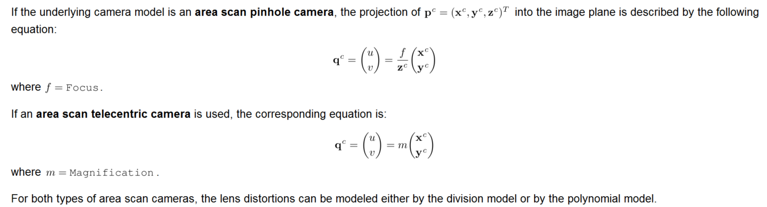
Area scan pinhole camera:
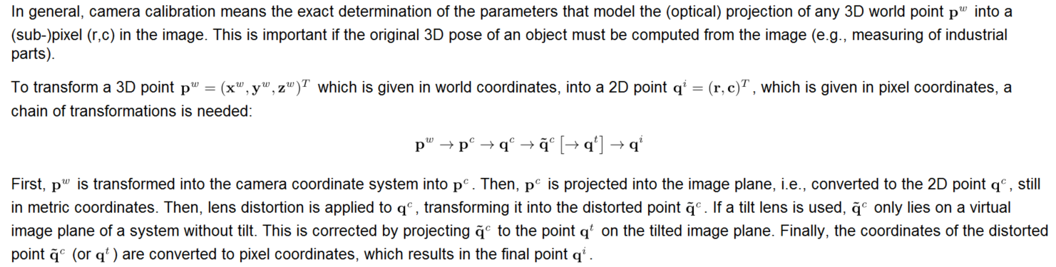
The combination of an area scan camera with a lens that effects a perspective projection on the object side of the lens and that may show radial and decentering distortions. The lens may be a tilt lens, i.e., the optical axis of the lens may be tilted with respect to the camera's sensor (this is sometimes called a Scheimpflug lens). The models for regular (i.e., non-tilt) pinhole and image-side telecentric lenses are identical. In contrast, the models for pinhole and image-side telecentric tilt lenses differ substantially, as described below.
Area scan telecentric camera:
The combination of an area scan camera with a lens that is telecentric on the object-side of the lens, i.e., that effects a parallel projection on the object-side of the lens, and that may show radial and decentering distortions. The lens may be a tilt lens. The models for regular (i.e., non-tilt) bilateral and object-side telecentric lenses are identical. In contrast, the models for bilateral and object-side telecentric tilt lenses differ substantially, as described below.
Line scan pinhole camera:
The combination of a line scan camera with a lens that effects a perspective projection and that may show radial distortions. Tilt lenses are currently not supported for line scan cameras.
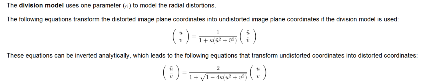
Division model
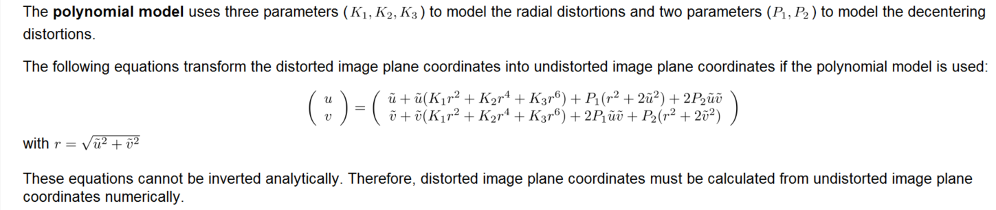
Polynomial model
tilt lens
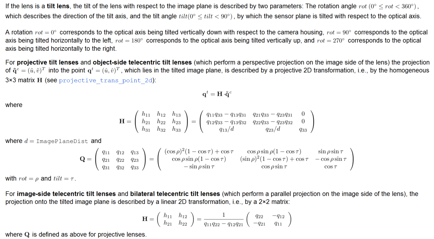
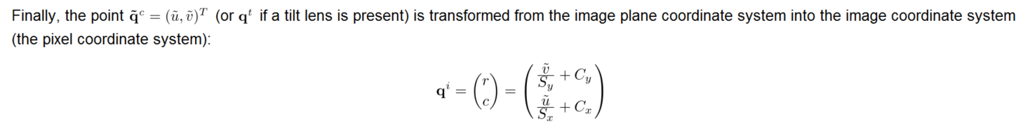
Image Coordinate-->Pixel Coordinate
Calibration
First, choose the description file for your calibration plate and the calibration plate Thickness (in mm). The name of the description file indicates the size of the plate and the file extension indicates the type of the calibration plate. In particular, the file ending .cpd is used for calibration plates with hexagonally arranged marks and the file extension .descr is used for calibration plates with rectangularly arranged marks. Note that calibration plates with hexagonally arranged marks usually have light marks on a dark background. Nevertheless, also calibration plates with dark marks on a light background are available. Then, you have to choose a description file with the filename ending "_dark_on_light". Calibration plates with rectangularly arranged marks always have dark marks on a light background. With the parameter Thickness, you can modify the position of the world coordinate system and the measurement plane, which is located beneath the calibration plate surface by the value of Thickness in the
Reference Image (page 195).
gen_caltab() Generate a calibration plate description file and a corresponding PostScript file for a calibration plate with rectangularly arranged marks.
生成的标定板的坐标系为:原点位于所有mark点的质心,z轴指向标定板内部,x轴向右,y轴向下。
生成的描述文件默认后缀名为descr,以#开始的行为注释行
create_caltab() Generate a calibration plate description file and a corresponding PostScript file for a calibration plate with hexagonally arranged marks.
The calibration plate contains one to five finder patterns. A finder pattern is a special mark hexagon (i.e. a mark and its six neighbors) where either four or six marks contain a hole. Each of these up to five finder patterns is unique such that it can be used to determine the orientation of the calibration plate and the position of the finder pattern on the calibration plate. As a consequence, the calibration plate can only be found by find_calib_object if at least one of these finder patterns is completely visible. The position of the central mark of each finder pattern is given in FinderRow and FinderColumn. Thus, the length of the tuples given in FinderRow and FinderColumn, respectively determine the number of finder patterns on the calibration plate. Be aware that two finder patterns must not overlap. It is recommended to keep a certain distance between the finder patterns. As a rule of thumb, if the calibration plate contains too little marks to place all finder patterns in distinct positions, it is better to reduce the number of finder patterns so that they can be distributed more evenly.
The coordinate system of the calibration plate is located at the center of the central mark of the first finder pattern.
Depending on Polarity the marks are either light on dark background (for 'light_on_dark', which is the default) or dark on light background (for 'dark_on_light').
caltab_points() Read the mark center points from the calibration plate description file.
create_calib_data() 创建一个halcon标定数据模型
set_calib_data_cam_param() 设置标定模型的初始参数值
set_calib_data_calib_object() 指定标定数据模型的标定板描述文件
find_calib_object() Find the halcon calibration plate and set the extracted points and contours in a calibration data model.
get_calib_data() Query data stored or computed in a calibration data model.
get_calib_data_observ_points() Get point-based observation data from a calibration data model.
get_calib_data_observ_contours() Get contour-based observation data from a calibration data model.
calibrate_cameras() 计算标定数据模型的相机内外参数,The root mean square error (RMSE) of the back projection of the optimization is returned in Error (in pixels). The error gives a general indication whether the optimization was successful.
When using a standard HALCON calibration plate, the world coordinate system is defined by the coordinate system of the calibration plate. For calibration plates with hexagonally arranged marks (see create_caltab), the origin of the coordinate system is located at the center of the central mark of the first finder pattern. For calibration plates with rectangularly arranged marks gen_caltab the origin is located in the middle of the surface of the calibration plate. In both cases, the z-axis of the coordinate system is pointing into the calibration plate, its x-axis is pointing to the right, and its y-axis is pointing downwards.
If a HALCON calibration plate is used, you can use the operator find_calib_object to determine initial values for all 6 parameters. Using HALCON calibration plates with rectangularly arranged marks (see gen_caltab), a combination of the two operators find_caltab and find_marks_and_pose will have the same effect.
image_points_to_world_plane( : : CameraParam, WorldPose, Rows, Cols, Scale : X, Y)
Transform image points into the plane z=0 of a world coordinate system.
contour_to_world_plane_xld(Contours : ContoursTrans : CameraParam, WorldPose, Scale : )
Transform an XLD contour into the plane z=0 of a world coordinate system.
clear_calib_data( : : CalibDataID : )
Free the memory of a calibration data model.
gen_cam_par_area_scan_division() Generate a camera parameter tuple for an area scan camera with distortions modeled by the division model.