一、静态路由的不足
静态路由适用于:小规模的网络、架构不怎么调整的网络、没有环路的网络
二、RIP协议工作过程
2.1、工作特点
n路由信息协议RIP(Routing Information Protocol)是一个真正的距离矢量路由选择协议。
n它每隔30秒就送出自己完整的路由表到所有激活的接口。
nRIP协议选择最佳路径的标准就是跳数,认为到达目标网络经过的路由器最少的路径就是最佳路径。
n默认它所允许的最大跳数为15跳,也就是说16跳的距离将被认为是不可达的。
n在小型网络中,RIP会运转良好,但是对于使用慢速WAN连接的大型网络或者安装有大量路由器的网络来说,它的效率就很低了。
补充:垃圾收集计算器失效的路由,120秒后,自动从路由表测地删除
2.2、工作过程
说明:目标网络是192.168.10.0/24网段
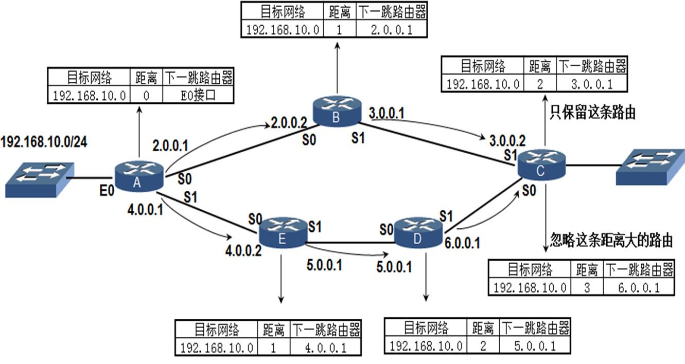
(1)、在A、B、C、D、E路由器上配置RIP协议,接下来我们从A路由器角度来看
(2)、由于192.168.10.0/24 网段就处在A路由器上,所以会生成一条路由条目如图所示,距离是0,接口是E0
(3)、A路由器每隔30秒就送出自己路由器里面的全部路由到B(使用广播)、E路由器
当B路由器B接收到A路由器发送来时,在B路由器就会把距离改为1,下一跳为2.0.0.1,;同理对于C路由器来说,接收到B路由器发送过来时,路由器距离变为2,下一跳路由3.0.0.1
当E路由器B接收到A路由器发送来时,在B路由器就会把距离改为1,下一跳为4.0.0.1,;同理对于D路由器来说,接收到E路由器发送过来时,路由器距离变为2,下一跳路由5.0.0.1;同理对于C路由器来说,接收到D路由器发送过来时,路由器距离变为3,下一跳路由6.0.0.1
(4)、由于从A-B-C线路过来的路由条目距离是2,从A-E-D-C线路过来的条目距离是3,2<3,所以会忽略距离是3的路由保留距离是2的路由条目
(5)、当AB路由器之间出现故障的导致B路由器在30秒之内收不到A路由器发送过来的路由条目,B路由器里面原来的路由条目(192.168.10.0 ;距离为2;下一跳是2.0.0.1) 就直接变为192.168.10.0,矢量距离变为最大距离16,下一跳是2.0.0.1
对于C路由器来说,通过RIP协议直接接收B路由器发送过来的路由条目,导致C路由条目改变为192.168.10.0 ,矢量距离16,下一跳是3.0.0.1
(6)、对于A-E-D-C路由线路没有受到影响,所以C收到的路由条目不变(目标网络192.168.10.0,矢量距离3,下一跳6.0.0.1)
(7)
从A-B-C线路过来,C路由条目是192.168.10.0,矢量距离是16,下一跳是3.0.0.1
从A-E-D-C线路过来,C路由条目是192.168.10.0,矢量距离是3,下一跳是6.0.0.1
矢量距离是16的自动删除,矢量距离是3的保存了下来
(8)、同理,如果A-B-C线路恢复的化,A-B-C线路又恢复初始状态
三、RIP协议配置和设置
配置RIP协议:
| 说明 | 命令 |
| 启用RIP协议、确定进程号 | [H3C]rip 进程号 |
| 使用network命令通告各网段 |
[H3C-rip-1]network 网段 |
| 显示RIP协议配置情况 | [H3C-rip-1]display this |
| 查看RIP协议学到的路由 | [H3C]display ip routing-table protocol rip |
| 显示RIP协议数据库 (显示动态路由协议到各网段的信息) | [H3C]display rip 1 database |
详细说明:
启用RIP协议、确定进程号
[H3C]rip 进程号
说明:设置RIP协议运行的进程号<每一个设备的进程号可以相同>
使用network命令通告各网段
[H3C-rip-1]network 网段
# 说明1
1、该网段的子网掩码是根据该网段的IP地址分类来默认的,所以不用写子网掩码
2、假如本来有两个网段(172.16.0.0 和172.16.5.0两个网段,但是该两个网段是同一类IP地址,所以其子网掩码是一样的,只写一个网段就OK)
# 说明2:
1、就要看接口属于哪个网络,多个接口属于同一个网段(按A、B、C分类),只需写一个
2、Network 用来配置路由器哪些接口参与到RIP协议
接口能够发送和接收RIP数据包
该接口所在的网段会被RIP协议通告出去
显示RIP协议配置情况
[H3C-rip-1]display this
# 示列:
rip 1
network 172.16.0.0
network 192.168.0.0
#
return
查看RIP协议学到的路由
[R1]display ip routing-table protocol rip
<Active> : 活跃,代表正在使用的
<Inactive>:不活跃,代表没有用的,没有放到路由表里面去的
显示RIP协议数据库(显示动态路由协议到各网段的信息)
[H3C]display rip 1 database
172.16.0.0/16, auto-summary
172.16.0.0/24, cost 0, nexthop 172.16.0.1, RIP-interface
172.16.1.0/24, cost 1, nexthop 172.16.0.2
172.16.2.0/24, cost 2, nexthop 172.16.0.2
172.16.3.0/24, cost 2, nexthop 172.16.0.2
172.16.3.0/24, cost 2, nexthop 172.16.5.2
172.16.4.0/24, cost 1, nexthop 172.16.5.2
172.16.5.0/24, cost 0, nexthop 172.16.5.1, RIP-interface
192.168.0.0/24, auto-summary
192.168.0.0/24, cost 0, nexthop 192.168.0.1, RIP-interface
查看运行的RIP协议
| 说明 | 命令 |
| 显示RIP协议学到的路由 |
<H3C>display ip routing-table protocol rip <AH3C>display rip 1 route |
| 显示RIP 1的配置 | <H3C>display rip 1 |
| 显示运行RIP协议的接口 | <H3C>display rip 1 interface |
查看/监控RIP协议活动情况
| 说明 | 命令 |
|
显示RIP协议活动状态 |
<R1>terminal monitor <R1>terminal debugging |
| 显示所有接口发送和接收的RIP包 | <R1>debugging rip 1 packet |
| 只显示G0/0/0接口发送和接收的RIP包 | <R1>debugging rip 1 packet GigabitEthernet 0/0/0 |
| 关闭所有诊断输出 | <R1>undo debugging all |
四、RIP协议中network的作用(怎么写network)
写network方法说明:
1、就要看接口属于哪个网络,多个接口属于同一个网段(按A、B、C分类),只需写一个。
2、Network 用来配置路由器哪些接口参与到RIP协议
接口能够发送和接收RIP数据包
该接口所在的网段会被RIP协议通告出去
示列1:
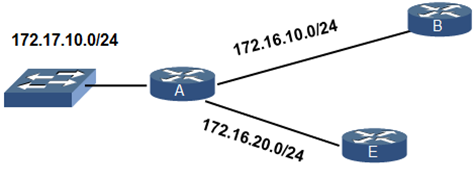
上图示列:network应该怎么写
方法一:全写(每个网段都写)
[RA] network 172.16.10.0
[RA] network 172.16.20.0
[RA] network 172.17.10.0
方法二:由于与路由器相连的三个网络中,有两个网段都是属于同一类网络(B类网络),可以写为一条network
[RA] network 172.17.0.0
[RA] network 172.16.0.0
示列2:
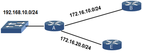
上图示列:network应该怎么写
方法一:全写(每个网段都写)
[RA] network 172.16.10.0
[RA] network 172.16.20.0
[RA] network 192.168.10.0
方法二:由于与路由器相连的三个网络中,有两个网段都是属于同一类网络(B类网络),可以写为一条network
[RA] network 172.16.0.0
[RA] network 192.168.10.0
五、配置路由器接口不发送RIP路由更新(可以优化网络)
1、配置场景
(1)、对于路由器一端只是接了交换机的一端,在默认配置RIP协议的时候也会把这个接口配置进去,这这样的做法是不对的,那么怎么一个怎么操作才能使用这个单一的接口不发送路由更新(这个设备的其他接口正常发送路由更新)
(2)、对于两个公司连接的两台路由器我们不希望把自己公司的rip路由协议通过给别的公司,可以在连接的该台设备上的对外的接口设置为不发送rip路由协议(公司的网关设置也是一样)
2、配置思路和命令
方法一:在rip 1 进程上面进行关闭该接口的rip协议
[R1]rip 1
[R1-rip-1]silent-interface GigabitEthernet 0/0   [想要开启的话,在前面直接加一个no就好了]
方法二:进入该接口,在接口上设置关闭rip发送功能
[R1]interface GigabitEthernet 0/0
[R1-GigabitEthernet0/0]rip
[R1-GigabitEthernet0/0]no rip output  [不知道命令的话,可以使用rip ?查看帮助手册]
说明:在配置的时候最好打开监控功能
3、配置案例
参考本章最后面案例1
六、RIPv2支持变长子网和身份验证
1、RIPv1和RIPv2的优缺点比较
| 分类 | 说明 | 等长子网 | 变长子网 |
| RIPv1 |
1、通过广播255.255.255.255 FF-FF-FF-FF-FF-FF 影响到电脑性能 |
推荐使用 |
不推荐使用 (使用RIPv1版本学到的路由的错误的) |
|
RIPv2 (推荐) |
1、通过多播224.0.0.9 多播MAC地址 不影响电脑的性能 |
不推荐使用 (使用RIPv2版本学到的路由的错误的) |
推荐使用 |
2、RIPv1和RIPv2版本查看/切换命令
版本查看命令:
方法一:进入进程查看
[R2]rip 1
[R2-rip-1]display this
#
rip 1
 version 2
 network 192.168.10.0
#
return
[R2-rip-1]

方法二:通过监控调试命令行查看
<R2>terminal monitor
The current terminal is enabled to display logs.
<R2>terminal debugging
The current terminal is enabled to display debugging logs.
<R2>debugging rip 1 packet interface GigabitEthernet 0/0
<R2>*Jun 19 12:02:24:160 2019 R2 RIP/7/RIPDEBUG: RIP 1 : Sending response on interface GigabitEthernet0/0 from 192.168.10.2 to 224.0.0.9
*Jun 19 12:02:24:160 2019 R2 RIP/7/RIPDEBUG: Packet: version 2, cmd response, length 64
*Jun 19 12:02:24:160 2019 R2 RIP/7/RIPDEBUG: AFI 2, destination 192.168.10.4/255.255.255.252, nexthop 0.0.0.0, cost 1, tag 0
*Jun 19 12:02:24:160 2019 R2 RIP/7/RIPDEBUG: AFI 2, destination 192.168.10.32/255.255.255.224, nexthop 0.0.0.0, cost 2, tag 0
<R2>no no terminal all # 关闭接口调试
版本切换命令:version
[R2]rip 1
[R2-rip-1]display this
#
rip 1
 version 2
 network 192.168.10.0
#
return
[R2-rip-1]version 1 <假如当前版本是2版本,我们需要切换成1版本>
3、RIPv2功能介绍案例(不连续子网)
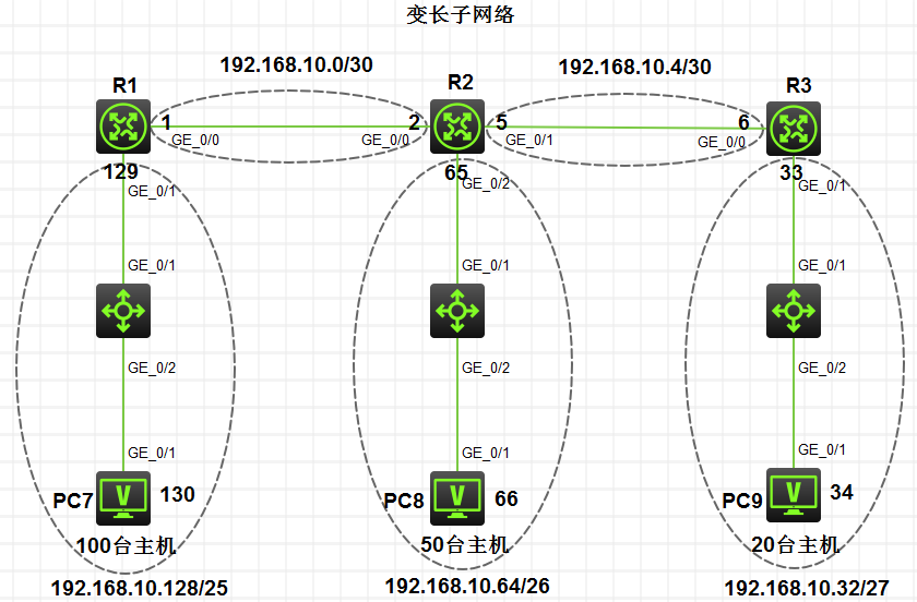
步骤1:IP地址配置


PC7:
    192.168.10.130
    255.255.255.128
    192.168.10.129
PC8
    192.168.10.66
    255.255.255.192
    192.168.10.65
PC9
    192.168.10.34
    255.255.255.224
    192.168.10.33
R1:
    [R1]hostname R1
    [R1]interface GigabitEthernet 0/1
    [R1-GigabitEthernet0/1]ip address 192.168.10.129 25
    [R1]interface GigabitEthernet 0/0
    [R1-GigabitEthernet0/0]ip address 192.168.10.1 30
    [R1]ping 192.168.10.130
    [R1]ping 192.168.10.2
R2
    [H3C]hostname R2
    [R2]interface GigabitEthernet 0/2
    [R2-GigabitEthernet0/2]ip address 192.168.10.65 26
    [R2]interface GigabitEthernet 0/1
    [R2-GigabitEthernet0/1]ip address 192.168.10.5 30
    [R2]interface GigabitEthernet 0/0
    [R2-GigabitEthernet0/0]ip address 192.168.10.2 30
    [R2]ping 192.168.10.1
    [R2]ping 192.168.10.6
    [R2]ping 192.168.10.66
R3
    [H3C]hostname R3
    [R3]interface GigabitEthernet 0/0
    [R3-GigabitEthernet0/0]ip address 192.168.10.6 30
    [R3-GigabitEthernet0/0]quit
    [R3]interface GigabitEthernet 0/1
    [R3-GigabitEthernet0/1]ip address 192.168.10.33 27
    [R3-GigabitEthernet0/1]ping 192.168.10.33
    [R3-GigabitEthernet0/1]ping 192.168.10.5
步骤2:配置RIP协议
R1:
    [R1]rip 1
    [R1-rip-1]network 192.168.10.0
R2:
    [R2]rip 1
    [R2-rip-1]network 192.168.10.0
R3:
    [R3]rip 1
    [R3-rip-1]network 192.168.10.0
步骤3:查看路由表(以R2为示列),是否学到了到各网段的路由
    [R2-rip-1]display ip routing-table protocol rip

    Summary count : 3

    RIP Routing table status : <Active>   # 这里为空,说明未学到路由
    Summary count : 0

    RIP Routing table status : <Inactive>
    Summary count : 3

    Destination/Mask   Proto   Pre Cost        NextHop         Interface
    192.168.10.0/30    RIP     100 0           0.0.0.0         GE0/0
    192.168.10.4/30    RIP     100 0           0.0.0.0         GE0/1
    192.168.10.64/26   RIP     100 0           0.0.0.0         GE0/2
总结:总结:由于路由器默认的RIP协议是1版本的RIPv1协议,因为RIPv1协议不支持变长子
步骤4:修改RIP协议版本(修改的时候,记得全部路由器都需要修改)
 R1:
    [R1]rip 1
    [R1-rip-1]network 192.168.10.0
R2:
    [R2]rip 1
    [R2-rip-1]network 192.168.10.0
R3:
    [R3]rip 1
    [R3-rip-1]network 192.168.10.0
步骤5:再次查看路由表
[R2]display ip routing-table protocol rip
[R2]display ip routing-table protocol rip

    Summary count : 5

    RIP Routing table status : <Active>
    Summary count : 2

    Destination/Mask   Proto   Pre Cost        NextHop         Interface
    192.168.10.32/27   RIP     100 1           192.168.10.6    GE0/1
    192.168.10.128/25  RIP     100 1           192.168.10.1    GE0/0   #已经学到了两个网段的路由条目了

    RIP Routing table status : <Inactive>
    Summary count : 3

    Destination/Mask   Proto   Pre Cost        NextHop         Interface
    192.168.10.0/30    RIP     100 0           0.0.0.0         GE0/0
    192.168.10.4/30    RIP     100 0           0.0.0.0         GE0/1
    192.168.10.64/26   RIP     100 0           0.0.0.0         GE0/2
步骤6:进行ping测试,
[R2]ping 192.168.10.34
[R2]ping 192.168.10.34
说明:如果能够正常ping通,代表链路正常
步骤7:RIPv2支持身份验证功能测试
身份证验证功能说明:身份验证功能是针对路由器和路由器相连的两个接口的身份验证,如果设置了密码连接的两个接口且验证的密码必须要相同
验证功能配置命令:
需要R1的0/0接口和R2的0/0接口密码相同,R2的0/1和R3的0/0密码相同
R1:
  [R1]interface GigabitEthernet 0/0
  [R1-GigabitEthernet0/0]rip authentication-mode simple plain 1234
R2:
  [R2]interface GigabitEthernet 0/0
  [R2-GigabitEthernet0/0]rip authentication-mode simple plain 1234
  [R2]interface GigabitEthernet 0/1
  [R2-GigabitEthernet0/1]rip authentication-mode simple plain abcd
R3
  [R3]interface GigabitEthernet 0/0
七、RIP协议的自动汇总
1、连续子网和不连续子网区别
连续子网:由同一主网划分的多个子网连续,没有被其它多个网络隔开。
不连续子网:指在一个网络中,某几个连续由同一主网划分的子网中间被1个或多个其它网段的子网或网络隔开了,对于不连续子网来说,RIP协议会在类的边界进行路由的自动汇总
2、关闭RIP协议的自动汇总功能(仅支持不连续子网)

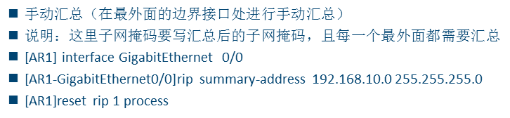
3、RIP协议的手动汇总
八、配置RIP协议发布默认路由
九、RIP协议定时器和防止环路的方法

十、动态路由协议的不足
案例1
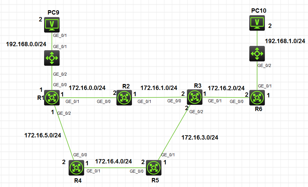
步骤1:配置各项IP地址
R1:
    [H3C]interface GigabitEthernet 0/0
    [H3C-GigabitEthernet0/0]ip address 192.168.0.1 24
    [H3C-GigabitEthernet0/0]no shutdown
    [H3C-GigabitEthernet0/0]quit

    [H3C]interface GigabitEthernet 0/1
    [H3C-GigabitEthernet0/1]ip address 172.16.0.1 24
    [H3C-GigabitEthernet0/1]no shutdown
    [H3C-GigabitEthernet0/1]quit

    [H3C]interface GigabitEthernet 0/2
    [H3C-GigabitEthernet0/2]ip address 172.16.5.1 24
    [H3C-GigabitEthernet0/2]no shutdown
    [H3C-GigabitEthernet0/2]quit
    [H3C]hostname R1

R2:
    [H3C]hostname R2
    [R2]interface GigabitEthernet 0/0
    [R2-GigabitEthernet0/0]ip address 172.16.0.2 24
    [R2-GigabitEthernet0/0]no shutdown
    [R2-GigabitEthernet0/0]quit

    [R2]interface GigabitEthernet 0/1
    [R2-GigabitEthernet0/1]ip address 172.16.1.1 24
    [R2-GigabitEthernet0/1]no shutdown
    [R2-GigabitEthernet0/1]quit

    [R2]ping 172.16.0.1   <测试R1和R2的连通性,如果能ping通的话,说明配置正常>


R3:

    [H3C]hostname R3
    [R3]interface GigabitEthernet 0/0
    [R3-GigabitEthernet0/0]ip address 172.16.1.2 24
    [R3-GigabitEthernet0/0]no shutdown
    [R3-GigabitEthernet0/0]quit

    [R3]interface GigabitEthernet 0/1
    [R3-GigabitEthernet0/1]ip address 172.16.2.1 24
    [R3-GigabitEthernet0/1]no shutdown
    [R3-GigabitEthernet0/1]quit

    [R3]interface GigabitEthernet 0/2
    [R3-GigabitEthernet0/2]ip address 172.16.3.2 24
    [R3-GigabitEthernet0/2]no shutdown
    [R3-GigabitEthernet0/2]quit

    [R3]ping 172.16.1.1    <测试R2和R3的连通性,如果能ping通的话,说明配置正常>

R4:
    [H3C]hostname R4
    [R4]interface GigabitEthernet 0/0
    [R4-GigabitEthernet0/0]ip address 172.16.5.2 24
    [R4-GigabitEthernet0/0]no shutdown
    [R4-GigabitEthernet0/0]ping 172.16.5.1   <测试R1和R4的连通性,如果能ping通的话,说明配置正常>
    [R4-GigabitEthernet0/0]quit

    [R4]interface GigabitEthernet 0/1
    [R4-GigabitEthernet0/1]ip address 172.16.4.1 24
    [R4-GigabitEthernet0/1]no shutdown
    [R4-GigabitEthernet0/1]quit

R5

    [H3C]hostname R5
    [R5]interface GigabitEthernet 0/0
    [R5-GigabitEthernet0/0]ip address 172.16.4.2 24
    [R5-GigabitEthernet0/0]no shutdown
    [R5-GigabitEthernet0/0]quit

    [R5]interface GigabitEthernet 0/1
    [R5-GigabitEthernet0/1]ip address 172.16.3.1 24
    [R5-GigabitEthernet0/1]no shutdown
    [R5-GigabitEthernet0/1]quit
    [R5]ping 172.16.4.1         <测试R4和R5的连通性,如果能ping通的话,说明配置正常>
    [R5]ping 172.16.3.2         <测试R2和R5的连通性,如果能ping通的话,说明配置正常>

R6:

    [H3C]hostname R6
    [R6]interface GigabitEthernet 0/0
    [R6-GigabitEthernet0/0]ip address 172.16.2.2 24
    [R6-GigabitEthernet0/0]no shutdown
    [R6-GigabitEthernet0/0]quit
    [R6]ping  172.16.2.1    <测试R3和R6的连通性,如果能ping通的话,说明配置正常>

    [R6]interface GigabitEthernet 0/1
    [R6-GigabitEthernet0/1]ip address 192.168.1.1 24
    [R6-GigabitEthernet0/1]no shutdown
    [R6-GigabitEthernet0/1]quit
    [R6]ping 192.168.1.2    <测试PC10和R6的连通性,如果能ping通的话,说明配置正常>

PC9:
    192.168.0.2
    255.255.255.0
    192.168.0.1

PC10
    192.168.1.2
    255.255.255.0
    192.168.1.1
步骤2:设置RIP协议
设定思路:

(1):启用RIP协议、确定进程号    # 设置RIP协议运行的进程号<每一个设备的进程号可以相同>
[H3C]rip 进程号
(2):使用network命令通告各网段   # 说明1:该网段的子网掩码是根据该网段的IP地址分类来默认的,所以不用写子网掩码
[H3C-rip-1]network 网段      # 说明2:假如本来有两个网段(172.16.0.0 和172.16.5.0两个网段,但是该两个网段是同一类IP地址,所以其子网掩码是一样的,只写一个网段就OK)

说明:
1、就要看接口属于哪个网络,多个接口属于同一个网段(按A、B、C分类),只需写一个
2、Network 用来配置路由器哪些接口参与到RIP协议
接口能够发送和接收RIP数据包
该接口所在的网段会被RIP协议通告出去


(3):显示RIP协议配置情况
[H3C-rip-1]display this
#
rip 1
network 172.16.0.0
network 192.168.0.0
#
return

(4):查看RIP协议学到的路由
[R1]display ip routing-table protocol rip
<Active> : 活跃,代表正在使用的
<Inactive>:不活跃,代表没有用的,没有放到路由表里面去的


(5):显示RIP协议数据库(显示动态路由协议到各网段的信息)
[H3C]display rip 1 database
配置命令:
R1路由器设定
  [R1-rip-1]network 192.168.0.0
  [R1-rip-1]network 172.16.0.0
R2路由器设定:
  [R2-rip-1]network 172.16.0.0
R3路由器设定:
  [R3-rip-1]network 172.16.0.0
R4路由器设定:
  [R4-rip-1]network 172.16.0.0
R5路由器设定:
  [R5-rip-1]network 172.16.0.0
R6路由器设定:
  [R6-rip-1]network 172.16.0.0
  [R6-rip-1]network 192.168.1.0
步骤3:进行测试
(1)配置好了之后,进行PC9 ——ping——> PC10 的测试,如果ping测试连通的话,代表配置没有问题(上面的配置没有问题)
(2)我们在R1上执行下面命令,查看动态路由协议到各网段的信息
[R1-rip-1]display rip 1 database
[R1-rip-1]display rip 1 database

  172.16.0.0/16, auto-summary
 172.16.0.0/24, cost 0, nexthop 172.16.0.1, RIP-interface
 172.16.1.0/24, cost 1, nexthop 172.16.0.2
 172.16.2.0/24, cost 2, nexthop 172.16.0.2
 172.16.3.0/24, cost 2, nexthop 172.16.5.2
 172.16.3.0/24, cost 2, nexthop 172.16.0.2
 172.16.4.0/24, cost 1, nexthop 172.16.5.2
 172.16.5.0/24, cost 0, nexthop 172.16.5.1, RIP-interface
 192.168.0.0/24, auto-summary
 192.168.0.0/24, cost 0, nexthop 192.168.0.1, RIP-interface
 192.168.1.0/24, auto-summary
 192.168.1.0/24, cost 3, nexthop 172.16.0.2 <这里是3,代表正常>
[R1-rip-1]ping 192.168.1.2 <能ping通代表正常>
(3)把R2的一个接口关闭(这里关闭0/1接口),这里要等待30S才能正常显示
[R2]interface GigabitEthernet 0/1
[R2-GigabitEthernet0/1]shutdown
再次到R1上面,查看动态路由协议到各网段的信息
[R1-rip-1]display rip 1 database
172.16.0.0/16, auto-summary
172.16.0.0/24, cost 0, nexthop 172.16.0.1, RIP-interface
172.16.1.0/24, cost 16, nexthop 172.16.0.2 <这里是16,代表正常。由于我们把R2断开了,所以从172.16.0.0网段到192.168.1.0链路出现问题,即变为16了>
172.16.2.0/24, cost 16, nexthop 172.16.0.2 <这里是16,代表正常。由于我们把R2断开了,所以从172.16.0.0网段到192.168.1.0链路出现问题,即变为16了>
172.16.3.0/24, cost 2, nexthop 172.16.5.2
172.16.4.0/24, cost 1, nexthop 172.16.5.2
172.16.5.0/24, cost 0, nexthop 172.16.5.1, RIP-interface
192.168.0.0/24, auto-summary
192.168.0.0/24, cost 0, nexthop 192.168.0.1, RIP-interface
192.168.1.0/24, auto-summary
192.168.1.0/24, cost 16, nexthop 172.16.0.2 <这里是16,代表正常。由于我们把R2断开了,所以从172.16.0.0网段到192.168.1.0链路出现问题,即变为16了>
[R1-rip-1]ping 192.168.1.2 <能ping通代表正常>
步骤4:配置诊断输出,修改错误的RIP,看显示的是什么情况<以R2为示列>
(1)、显示终端监控
<R2>terminal monitor
The current terminal is enabled to display logs.
(2)、输出终端debug
<R2>terminal debugging
The current terminal is enabled to display debugging logs.
(3)、查看R2上的rip 1 进程包的发送和接收情况
<R2>debugging rip 1 packet
<R2>debugging rip 1 packet
<R2>*Jun 18 18:47:32:011 2019 R2 RIP/7/RIPDEBUG: RIP 1 : Receiving response from 172.16.1.2 on GigabitEthernet0/1   # 到172.16.1.2地址的0/1接口RIP接收情况
*Jun 18 18:47:32:011 2019 R2 RIP/7/RIPDEBUG:   Packet: version 1, cmd response, length 84
*Jun 18 18:47:32:011 2019 R2 RIP/7/RIPDEBUG:     AFI 2, destination 172.16.2.0, cost 1
*Jun 18 18:47:32:011 2019 R2 RIP/7/RIPDEBUG:     AFI 2, destination 172.16.3.0, cost 1
*Jun 18 18:47:32:011 2019 R2 RIP/7/RIPDEBUG:     AFI 2, destination 172.16.4.0, cost 2
*Jun 18 18:47:32:011 2019 R2 RIP/7/RIPDEBUG:     AFI 2, destination 192.168.1.0, cost 2
*Jun 18 18:47:39:154 2019 R2 RIP/7/RIPDEBUG: RIP 1 : Receiving response from 172.16.0.1 on GigabitEthernet0/0        # 到172.16.0.1地址的0/0接口RIP发送情况
*Jun 18 18:47:39:154 2019 R2 RIP/7/RIPDEBUG:   Packet: version 1, cmd response, length 64
*Jun 18 18:47:39:154 2019 R2 RIP/7/RIPDEBUG:     AFI 2, destination 172.16.4.0, cost 2
*Jun 18 18:47:39:154 2019 R2 RIP/7/RIPDEBUG:     AFI 2, destination 172.16.5.0, cost 1
*Jun 18 18:47:39:154 2019 R2 RIP/7/RIPDEBUG:     AFI 2, destination 192.168.0.0, cost 1
*Jun 18 18:47:40:318 2019 R2 RIP/7/RIPDEBUG: RIP 1 : Sending response on interface GigabitEthernet0/0 from 172.16.0.2 to 255.255.255.255
*Jun 18 18:47:40:318 2019 R2 RIP/7/RIPDEBUG:   Packet: version 1, cmd response, length 84
*Jun 18 18:47:40:318 2019 R2 RIP/7/RIPDEBUG:     AFI 2, destination 172.16.1.0, cost 1
*Jun 18 18:47:40:318 2019 R2 RIP/7/RIPDEBUG:     AFI 2, destination 172.16.2.0, cost 2
*Jun 18 18:47:40:318 2019 R2 RIP/7/RIPDEBUG:     AFI 2, destination 172.16.3.0, cost 2
*Jun 18 18:47:40:318 2019 R2 RIP/7/RIPDEBUG:     AFI 2, destination 192.168.1.0, cost 3        # 未删除network 192.168.1.0
*Jun 18 18:47:40:318 2019 R2 RIP/7/RIPDEBUG: RIP 1 : Sending response on interface GigabitEthernet0/1 from 172.16.1.1 to 255.255.255.255
*Jun 18 18:47:40:318 2019 R2 RIP/7/RIPDEBUG:   Packet: version 1, cmd response, length 64
*Jun 18 18:47:40:318 2019 R2 RIP/7/RIPDEBUG:     AFI 2, destination 172.16.0.0, cost 1
*Jun 18 18:47:40:318 2019 R2 RIP/7/RIPDEBUG:     AFI 2, destination 172.16.5.0, cost 2
*Jun 18 18:47:40:318 2019 R2 RIP/7/RIPDEBUG:     AFI 2, destination 192.168.0.0, cost 2
(4)、把R6上面的network 192.168.1.0 网段删除,看R2上面是否有什么变化
①:删除R6上面的192.168.1.0网段的network
[R6] system-view
[R6] rip 1
[R6-rip-1]display this
#
rip 1
network 172.16.0.0
network 192.168.1.0
#
return
[R6-rip-1]no network 192.168.1.0 [删除192.168.1.0网段的network]
[R6-rip-1]display this
#
rip 1
network 172.16.0.0
#
return
②、查看R2上面有什么变化
<R2>terminal monitor
The current terminal is enabled to display logs.
<R2>terminal debugging
The current terminal is enabled to display debugging logs.
<R2>debugging rip 1 packet
<R2>debugging rip 1 packet
*Jun 18 18:57:13:548 2019 R2 RIP/7/RIPDEBUG: RIP 1 : Receiving response from 172.16.1.2 on GigabitEthernet0/1
*Jun 18 18:57:13:548 2019 R2 RIP/7/RIPDEBUG:   Packet: version 1, cmd response, length 84
*Jun 18 18:57:13:548 2019 R2 RIP/7/RIPDEBUG:     AFI 2, destination 172.16.2.0, cost 1
*Jun 18 18:57:13:548 2019 R2 RIP/7/RIPDEBUG:     AFI 2, destination 172.16.3.0, cost 1
*Jun 18 18:57:13:548 2019 R2 RIP/7/RIPDEBUG:     AFI 2, destination 172.16.4.0, cost 2
*Jun 18 18:57:13:548 2019 R2 RIP/7/RIPDEBUG:     AFI 2, destination 192.168.1.0, cost 16
<R2>terminal m*Jun 18 18:56:59:317 2019 R2 RIP/7/RIPDEBUG: RIP 1 : Sending response on interface GigabitEthernet0/0 from 172.16.0.2 to 255.255.255.255
*Jun 18 18:56:59:317 2019 R2 RIP/7/RIPDEBUG:   Packet: version 1, cmd response, length 84
*Jun 18 18:56:59:317 2019 R2 RIP/7/RIPDEBUG:     AFI 2, destination 172.16.1.0, cost 1
*Jun 18 18:56:59:317 2019 R2 RIP/7/RIPDEBUG:     AFI 2, destination 172.16.2.0, cost 2
*Jun 18 18:56:59:317 2019 R2 RIP/7/RIPDEBUG:     AFI 2, destination 172.16.3.0, cost 2
*Jun 18 18:56:59:317 2019 R2 RIP/7/RIPDEBUG:     AFI 2, destination 192.168.1.0, cost 16    # 删除network 192.168.1.0就直接变为16,在过段时间就从路由器上面自动删除了
*Jun 18 18:56:59:317 2019 R2 RIP/7/RIPDEBUG: RIP 1 : Sending response on interface GigabitEthernet0/1 from 172.16.1.1 to 255.255.255.255
*Jun 18 18:56:59:317 2019 R2 RIP/7/RIPDEBUG:   Packet: version 1, cmd response, length 64
*Jun 18 18:56:59:317 2019 R2 RIP/7/RIPDEBUG:     AFI 2, destination 172.16.0.0, cost 1
*Jun 18 18:56:59:317 2019 R2 RIP/7/RIPDEBUG:     AFI 2, destination 172.16.5.0, cost 2
*Jun 18 18:56:59:317 2019 R2 RIP/7/RIPDEBUG:     AFI 2, destination 192.168.0.0, cost 2
*Jun 18 18:57:13:760 2019 R2 RIP/7/RIPDEBUG: RIP 1 : Receiving response from 172.16.0.1 on GigabitEthernet0/0
*Jun 18 18:57:13:760 2019 R2 RIP/7/RIPDEBUG:   Packet: version 1, cmd response, length 64
*Jun 18 18:57:13:760 2019 R2 RIP/7/RIPDEBUG:     AFI 2, destination 172.16.4.0, cost 2
*Jun 18 18:57:13:760 2019 R2 RIP/7/RIPDEBUG:     AFI 2, destination 172.16.5.0, cost 1
*Jun 18 18:57:13:760 2019 R2 RIP/7/RIPDEBUG:     AFI 2, destination 192.168.0.0, cost 1
③、恢复R6的network
[R6] system-view

[R6] rip 1
[R6-rip-1]network 192.168.1.0
[R6-rip-1]display this
#
rip 1
network 172.16.0.0
network 192.168.1.0
#
return
步骤5、配置路由器接口不发送RIP路由更新
第一步:开启监控模式,监控R1上0/0接口单一的监控
<R1>terminal monitor
The current terminal is enabled to display logs.
<R1>terminal debugging
The current terminal is enabled to display debugging logs.
<R1>debugging rip 1 packet interface GigabitEthernet 0/0

第二步:关闭R1路由器0/0接口发送rip协议更新
方法一:在rip 1 进程上面进行关闭
[R1]rip 1
[R1-rip-1]silent-interface GigabitEthernet 0/0   [想要开启的话,在前面直接加一个no就好了]
方法二:进入0/0接口,在接口上设置关闭rip发送功能
[R1]interface GigabitEthernet 0/0
[R1-GigabitEthernet0/0]rip
[R1-GigabitEthernet0/0]no rip output  [不知道命令的话,可以使用rip ?查看帮助手册]
第三步:关闭监控模式
<R1>no debugging all