16.Given several input vectors, concatenate them together then split them up into several output vectors. There are six 5-bit input vectors: a, b, c, d, e, and f, for a total of 30 bits of input. There are four 8-bit output vectors: w, x, y, and z, for 32 bits of output. The output should be a concatenation of the input vectors followed by two 1 bits:

module top_module (
    input [4:0] a, b, c, d, e, f,
    output [7:0] w, x, y, z );//

    // assign { ... } = { ... };
    assign {w,x,y,z}={a,b,c,d,e,f,2'b11};
endmodule
17.Given an 8-bit input vector [7:0], reverse its bit ordering.(注意顺序!!!)
module top_module(
    input [7:0] in,
    output [7:0] out
);
    assign out={in[0],in[1],in[2],in[3],in[4],in[5],in[6],in[7]};
endmodule
18.One common place to see a replication operator is when sign-extending a smaller number to a larger one, while preserving its signed value. This is done by replicating the sign bit (the most significant bit) of the smaller number to the left. For example, sign-extending 4'b0101 (5) to 8 bits results in 8'b00000101 (5), while sign-extending 4'b1101 (-3) to 8 bits results in 8'b11111101 (-3).
Build a circuit that sign-extends an 8-bit number to 32 bits. This requires a concatenation of 24 copies of the sign bit (i.e., replicate bit[7] 24 times) followed by the 8-bit number itself.
module top_module (
    input [7:0] in,
    output [31:0] out
);

    // Concatenate two things together:
    // 1: {in[7]} repeated 24 times (24 bits)
    // 2: in[7:0] (8 bits)
    assign out = { {24{in[7]}}, in };

endmodule
19.Given five 1-bit signals (a, b, c, d, and e), compute all 25 pairwise one-bit comparisons in the 25-bit output vector. The output should be 1 if the two bits being compared are equal.
out[24] = ~a ^ a;   // a == a, so out[24] is always 1.
out[23] = ~a ^ b;
out[22] = ~a ^ c;
...
out[ 1] = ~e ^ d;
out[ 0] = ~e ^ e;

As the diagram shows, this can be done more easily using the replication and concatenation operators.
- The top vector is a concatenation of 5 repeats of each input
- The bottom vector is 5 repeats of a concatenation of the 5 inputs
module top_module (
    input a, b, c, d, e,
    output [24:0] out );//

    // The output is XNOR of two vectors created by
    // concatenating and replicating the five inputs.
    // assign out = ~{ ... } ^ { ... };
    assign out[24:20]=~{5{a}}^{a,b,c,d,e};
    assign out[19:15]=~{5{b}}^{a,b,c,d,e};
    assign out[14:10]=~{5{c}}^{a,b,c,d,e};
    assign out[9:5]=~{5{d}}^{a,b,c,d,e};
    assign out[4:0]=~{5{e}}^{a,b,c,d,e};
endmodule


//anwser:
module top_module (
    input a, b, c, d, e,
    output [24:0] out
);

    wire [24:0] top, bottom;
    assign top    = { {5{a}}, {5{b}}, {5{c}}, {5{d}}, {5{e}} };
    assign bottom = {5{a,b,c,d,e}};
    assign out = ~top ^ bottom;    // Bitwise XNOR

    // This could be done on one line:
    // assign out = ~{ {5{a}}, {5{b}}, {5{c}}, {5{d}}, {5{e}} } ^ {5{a,b,c,d,e}};

endmodule
20.In this exercise, create one instance of module mod_a, then connect the module's three pins (in1, in2, and out) to your top-level module's three ports (wires a, b, and out). The module mod_a is provided for you — you must instantiate it.You may connect signals to the module by port name or port position. For extra practice, try both methods.
module top_module (
    input a,
    input b,
    output out
);

    // Create an instance of "mod_a" named "inst1", and connect ports by name:
    mod_a inst1 (
        .in1(a),     // Port"in1"connects to wire "a"
        .in2(b),    // Port "in2" connects to wire "b"
        .out(out)    // Port "out" connects to wire "out"
                // (Note: mod_a's port "out" is not related to top_module's wire "out".
                // It is simply coincidence that they have the same name)
    );

/*
    // Create an instance of "mod_a" named "inst2", and connect ports by position:
    mod_a inst2 ( a, b, out );    // The three wires are connected to ports in1, in2, and out, respectively.
*/

endmodule
21.This problem is similar to the previous one (module). You are given a module named mod_a that has 2 outputs and 4 inputs, in that order. You must connect the 6 ports by position to your top-level module's ports out1, out2, a, b, c, and d, in that order.
You are given the following module:
module mod_a ( output, output, input, input, input, input );
module top_module (
    input a,
    input b,
    input c,
    input d,
    output out1,
    output out2
);
    mod_a inst1 (
        out1,
        out2,
        a,
        b,
        c,
        d);
endmodule
22.This problem is similar to module. You are given a module named mod_a that has 2 outputs and 4 inputs, in some order. You must connect the 6 ports by name to your top-level module's ports:
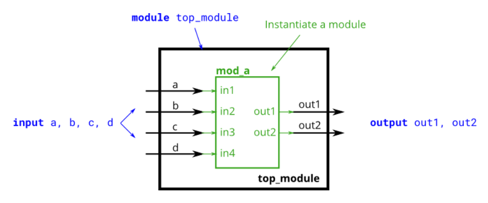
You are given the following module:
module mod_a ( output out1, output out2, input in1, input in2, input in3, input in4);
module top_module (
    input a,
    input b,
    input c,
    input d,
    output out1,
    output out2
);
    mod_a inst1 (
        .in1(a),
        .in2(b),
        .in3(c),
        .in4(d),
        .out1(out1),
        .out2(out2)
    );
endmodule
23.You are given a module my_dff with two inputs and one output (that implements a D flip-flop). Instantiate three of them, then chain them together to make a shift register of length 3. The clk port needs to be connected to all instances.
The module provided to you is: module my_dff ( input clk, input d, output q );
Note that to make the internal connections, you will need to declare some wires. Be careful about naming your wires and module instances: the names must be unique.

module top_module (
    input clk,
    input d,
    output q
);

    wire a, b;    // Create two wires. I called them a and b.

    // Create three instances of my_dff, with three different instance names (d1, d2, and d3).
    // Connect ports by position: ( input clk, input d, output q)
    my_dff d1 ( clk, d, a );
    my_dff d2 ( clk, a, b );
    my_dff d3 ( clk, b, q );

endmodule
24.The module provided to you is: module my_dff8 ( input clk, input [7:0] d, output [7:0] q );
The multiplexer is not provided. One possible way to write one is inside an always block with a case statement inside.

module top_module (
    input clk,
    input [7:0] d,
    input [1:0] sel,
    output reg [7:0] q
);

    wire [7:0] o1, o2, o3;        // output of each my_dff8
    // Instantiate three my_dff8s
    my_dff8 d1 ( clk, d, o1 );
    my_dff8 d2 ( clk, o1, o2 );
    my_dff8 d3 ( clk, o2, o3 );

    // This is one way to make a 4-to-1 multiplexer
    always @(*)        // Combinational always block
        case(sel)
            2'h0: q = d;
            2'h1: q = o1;
            2'h2: q = o2;
            2'h3: q = o3;
        endcase
endmodule
25.onnect the modules together as shown in the diagram below. The provided module add16 has the following declaration:
module add16 ( input[15:0] a, input[15:0] b, input cin, output[15:0] sum, output cout );

module top_module(
    input [31:0] a,
    input [31:0] b,
    output [31:0] sum
);
    wire cin1,cout1,cout2;
    wire [15:0] sum1,sum2;
    assign cin1=1'b0;
    add16 inst1 (a[15:0],b[15:0],cin1,sum1,cout1);
    add16 inst2 (a[31:16],b[31:16],cout1,sum2,cout2);
    assign sum={sum2,sum1};
endmodule

//出错记录:忘了加assign。。
26.Connect the add16 modules together as shown in the diagram below. The provided module add16 has the following declaration:
module add16 ( input[15:0] a, input[15:0] b, input cin, output[15:0] sum, output cout );
Within each add16, 16 full adders (module add1, not provided) are instantiated to actually perform the addition. You must write the full adder module that has the following declaration:
module add1 ( input a, input b, input cin, output sum, output cout );
Recall that a full adder computes the sum and carry-out of a+b+cin.
In summary, there are three modules in this design:
top_module— Your top-level module that contains two of...add16, provided — A 16-bit adder module that is composed of 16 of...add1— A 1-bit full adder module.

module top_module (
    input [31:0] a,
    input [31:0] b,
    output [31:0] sum
);//
    wire [15:0] sum1,sum2;
    wire out1,out2,in1;
    assign in1=1'b0;
    add16 inst1 (a[15:0],b[15:0],in1,sum1,out1);
    add16 inst2 (a[31:16],b[31:16],out1,sum2,out2);
    assign sum={sum2,sum1};
endmodule

module add1 ( input a, input b, input cin, output sum, output cout );
// Full adder module here
    assign sum=a^b^cin;
    assign cout=(a|cin)&(b|cin)&(a|b);
endmodule
27.Connect the modules together as shown in the diagram below. The provided module add16 has the following declaration:
module add16 ( input[15:0] a, input[15:0] b, input cin, output[15:0] sum, output cout );

module top_module( input [31:0] a, input [31:0] b, output [31:0] sum);
    wire in1,in2,in3,o1,o2,o3;
    wire [15:0] sum1,sum2,sum3;
    assign in1=1'b0;
    assign in2=1'b0;
    assign in3=1'b1;
    add16 inst1 (a[15:0],b[15:0],in1,sum1,o1);
    add16 inst2 (a[31:16],b[31:16],in2,sum2,o2);
    add16 inst3 (a[31:16],b[31:16],in3,sum3,o3);
    always@(*)
        case(o1)
            1'b0:sum={sum2,sum1};
            1'b1:sum={sum3,sum1};
        endcase
endmodule
28.Use a 32-bit wide XOR gate to invert the b input whenever sub is 1. (This can also be viewed as b[31:0] XORed with sub replicated 32 times. See replication operator.). Also connect the sub input to the carry-in of the adder.

module top_module(
    input [31:0] a,
    input [31:0] b,
    input sub,
    output [31:0] sum
);
    wire cout1,cout2;
    wire [31:0] bin;
    wire [15:0] sum1,sum2;
    assign bin={32{sub}}^b;
    add16 inst1(a[15:0],bin[15:0],sub,sum1,cout1);
    add16 inst2(a[31:16],bin[31:16],cout1,sum2,cout2);
    assign sum={sum2,sum1};
endmodule
29.Build an AND gate using both an assign statement and a combinational always block. (Since assign statements and combinational always blocks function identically, there is no way to enforce that you're using both methods. But you're here for practice, right?...)

// synthesis verilog_input_version verilog_2001
module top_module(
    input a,
    input b,
    output wire out_assign,
    output reg out_alwaysblock
);
    assign out_assign = a & b;
    always @(*)
        out_alwaysblock = a & b;

endmodule
30.Build an XOR gate three ways, using an assign statement, a combinational always block, and a clocked always block. Note that the clocked always block produces a different circuit from the other two: There is a flip-flop so the output is delayed.

// synthesis verilog_input_version verilog_2001
module top_module(
    input clk,
    input a,
    input b,
    output wire out_assign,
    output reg out_always_comb,
    output reg out_always_ff   );
    assign out_assign=a^b;
    always@(*)
        out_always_comb=a^b;
    always@(posedge clk)
        out_always_ff<=a^b;
endmodule