Table of Contents
1.5 Constraints and Assumptions 1
2 High-Level POC Architecture 3
3.1 Sequence Diagram for Iaas & SaaS 4
5.1 Server Physical Infrastructure 7
5.1.1 Server Physical Machine Table 7
5.1.6 Remote Desktop Gateway Server (IBMH1) 8
5.1.7 Remote Desktop Gateway Server (IBMH2) 9
5.2 Server Virtual Infrastructure 9
5.2.2 Active Directory Server (DC1, DC3 & DC5) 10
5.2.3 System Center Virtual Machine Manager Server (SCVMM1) 11
5.2.4 System Center Operations Manager Server (SCOM01) 11
5.2.5 System Center Self Service Portal Server (SSP-V2) 11
5.2.6 Exchange CAS/HUB Server (CH1 and CH2) 12
5.2.7 Exchange Mailbox Server (MBX1, MBX2 & MBX3) 12
5.2.8 Hyper-V Server Cluster 12
5.3 Implementation of Design 12
5.7 Security Considerations 15
5.7.1 End User Access to the solution 15
5.7.2 Host Operating System Configuration 15
6.4 iSCSI Target Host Setup 20
6.5 Build R2 Hyper-V Core hosts 27
6.12 Installing System Centre Virtual Machine Manager 2008 R2 79
6.13 Individual SCVMM Install 101
6.14.1 System Requirements: Single-Machine Deployment Scenario 119
6.14.2 System Requirements: VMMSSP Website Component 120
6.14.3 System Requirements: VMMSSP Server Component 121
6.14.4 System Requirements: VMMSSP Database Component 122
6.14.5 Installing the Virtual Machine Manager Self-Service Portal 122
6.15 Exchange Installation 125
6.16 Exchange Configuration 139
6.17.1 Terms and Abbreviations 143
Appendix A – Hyper-V Host Server Farm Pattern 144
Appendix B – Host Cluster patterns 145
Node and File Share Majority 145
Appendix C – Network Architecture 147
Appendix D - Processor Architecture 148
Appendix E – Memory Architecture 149
Appendix G - Disk Redundancy Architecture 151
Appendix H - Fibre Channel Storage Area Network 152
Appendix I - Disk Controller or HBA Interface 153
Appendix J - Cluster Shared Volumes 154
Appendix K - System Center Virtual Machine Manager R2 2008 156
Virtual Machine Manager Server 156
Microsoft SQL Server Database 156
Delegated Management and Provisioning Web Portal 157
Appendix L – Hyper-V Overview 158
Appendix M – Hardware Architecture 159
Cluster Host Server Overview 161
The scope of this document is concerned with Microsoft technologies only.
Assumptions | Explanation |
Physical environment | It is assumed that a server environment exists with enough floor space, power, air conditioning, physical security etc. |
Stable network | It is assumed that the local and wide area network infrastructure which includes physical components switches, routers, cable etc. And the logical components like routing, broadcasts, collisions etc. Are stable and under control. Having an unstable network can result in unexpected behavior. |
Namespace | Maintain Isolated / Unique Namespace |
Network Support | Failover / Router / Configuration needs to be performed by IT staff. |
Constraints | Explanation |
DHCP Required | DHCP is required for VM Provisioning |
Network Bandwidth | 1 GB network bandwidth |
Multiple VLANS / NICS | Multiple VLANS / NICS required for Clustering, Live Migration and Heartbeat |
iSCSI Hardware | Required 500 GB – 1 TB on iSCSI |
Table 1: Constraints and Assumptions
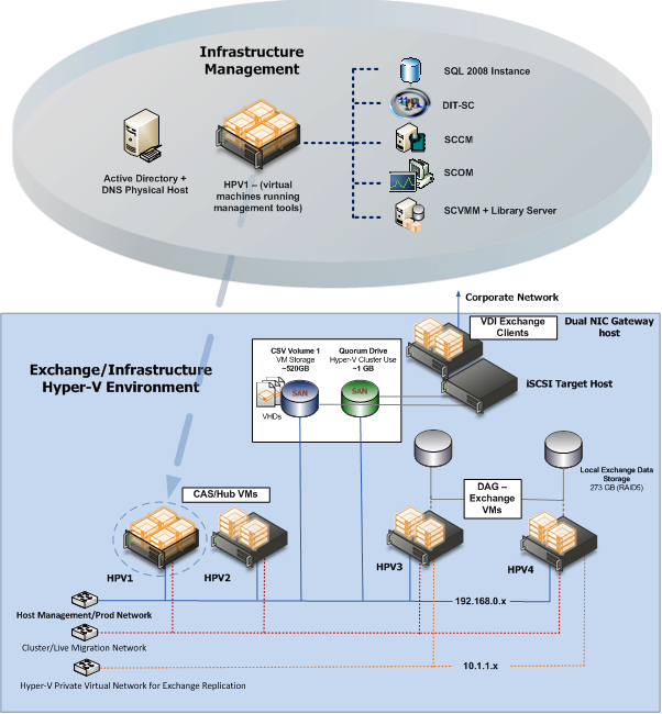
Figure 1: High Level POC Architecture
High-Level Showcase Scenarios (10-15) | |
IaaS (Dynamic Datacenter) | SaaS (Exchange) |
1. New tenant (organization) sign-up | 1. New tenant (organization) sign-up |
2. New environment provisioning request | 2. New tenant services configuration |
3. Virtual machine request | 3. Tenant admin set-up |
4. Virtual machine template setting | 4. New user (mailbox) addition |
5. Virtual machine provisioning | 5. Distribution list management rights assignment |
6. Reporting | 6. Charge back reporting |
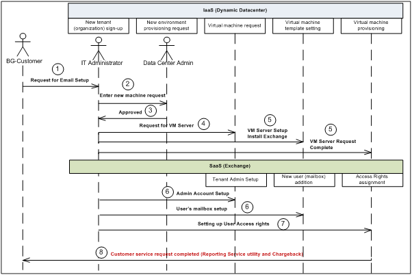
Figure 2: Sequence Diagram for Iaas & SaaS
Following are the sequence diagram steps
After you complete the procedures in this guide, continue to the Virtual Machine Manager 2008 R2 VMMSSP Datacenter Administration Guide (included in the self-service portal documentation package) for information about configuring the self-service portal and setting up services for business units. For more details please refer to the link http://www.microsoft.com/downloads/details.aspx?FamilyID=fef38539-ae5a-462b-b1c9-9a02238bb8a7&displaylang=en and download a file VMM08R2_VMMSSPDocumentation.zip for more information.
- Solution Design
The GPC-POC is based on a self-contained domain environment consisting of a number of management servers to support a scalable Hyper-V cluster onto which the solution will provision multiple Virtual Machines:
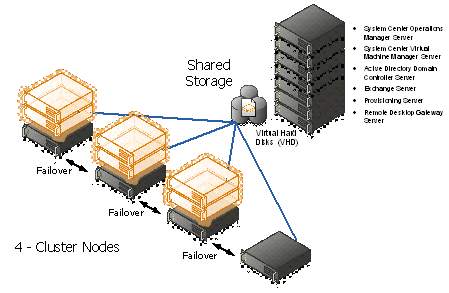
Figure 3: Hyper-V cluster Nodes with Virtual Machine
In order to make the solution as portable as possible, the management servers are themselves provided as virtual machines. This allows them to be scaled at the virtual host level to higher levels of memory/processor and disk as required without losing any portability.
The actual GPC-POC components in the handover consist only of the virtual machines making up the management servers. The associated Hyper-V Cluster needs to be created after the management servers are in place in the environment as it will need to be joined to the GPC-POC domain.
Providing a Hyper-V Cluster as the Virtualisation platform allows for fast transfer of the virtual machine servers to a different physical server in the event of unexpected hardware failure of the host. Live Migration will be used in the event of scheduled maintenance on the host servers and will provide continuous service with no outage or service loss.
The sections below covers the detailed configuration for the GPC-POC Infrastructure Environment.
- Server Physical Infrastructure
- Server Physical Machine Table
Base OS Server Name | Assigned Machine | Bits | RAM | CPU | Disks | Virtual Switch "Public" | Virtual Switch "Hyper-V & Exchange Replication" | Purpose |
HPB1 (HPV1) | HP Blade 1 | x64 | 64 GB | Quad Core | 2 X 150 GB (300 GB) | Gigabit Ethernet External NIC1 10.1.1.x VLAN1 Corp or VPN | Gigabit Ethernet External NIC2 10.1.2.x VLAN2 Lab internal | Hyper-V (cluster) DDC (SQL, DIT-SC, SCCM, SCOM, SCVMM + Library) Exchange CAS + Hub |
HPB2 (HPV2) | HP Blade 2 | x64 | 64 GB | Quad Core | 2 X 150 GB (300 GB) | Gigabit Ethernet External NIC1 10.1.1.x VLAN1 Corp or VPN | Gigabit Ethernet External NIC2 10.1.2.x VLAN2 Lab internal | Hyper-V failover for HPV1 |
HPB3 (HPV3) | HP Blade 3 | x64 | 32 GB | Quad Core | 2 X 150 GB (300 GB) | Gigabit Ethernet External NIC1 10.1.1.x VLAN1 Corp or VPN | Gigabit Ethernet External NIC2 10.1.2.x VLAN2 Lab internal | Hyper-V (cluster) DAS (273GB - RAID5) Exchange DAG |
HPB4 (HPV4) | HP Blade 4 | x64 | 32 GB | Quad Core | 2 X 150 GB (300 GB) | Gigabit Ethernet External NIC1 10.1.1.x VLAN1 Corp or VPN | Gigabit Ethernet External NIC2 10.1.2.x VLAN2 Lab internal | Hyper-V (cluster) DAS (273GB - RAID5) Exchange DAG |
IBMH1 | IBM 3850 + 2 Fusion IO cards | x64 | 16 GB | Quad Core Intel Xeon Series 7400 | 2 X 650 GB Fusion IO | Gigabit Ethernet External NIC1 10.1.1.x VLAN1 Corp or VPN | N/A | Hyper-V Dual NIC gateway host for remote access AD+DNS until Lenovo server is made available |
IBMH2 | IBM 3850 | x64 | 12 GB | Quad Core Intel Xeon Series 7400 |
| Gigabit Ethernet External NIC1 10.1.1.x VLAN1 Corp or VPN | N/A | iSCSI |
LENH1 | Lenovo RD210 | x64 | 8 GB |
|
| Gigabit Ethernet External NIC1 10.1.1.x VLAN1 Corp or VPN | N/A | Server missing hard drive and won't be available before week of June 21. AD+DNS |
Table 2: Server Physical Machine Table
For more details on the lab configuration, please refer the Excel sheet attached in the Appendix N
- HPV1
Following are the services installed on HPV1 VM Server
- Hyper-V (cluster)
- DDC (SQL, DIT-SC, SCCM, SCOM, SCVMM + Library)
- Exchange CAS + Hub
- HPV2
Following are the services installed on HPV2 VM Server. It's Hyper-V failover for HPV1
- Hyper-V (cluster)
- DDC (SQL, DIT-SC, SCCM, SCOM, SCVMM + Library)
- Exchange CAS + Hub
- HPV3
Following are the services installed on HPV3 VM Server
- Hyper-V (cluster)
- DAS (273GB - RAID5)
- Exchange DAG
- HPV4
Following are the services installed on HPV3 VM Server
- Hyper-V (cluster)
- DAS (273GB - RAID5)
- Exchange DAG
- Remote Desktop Gateway Server (IBMH1)
The Remote Desktop Gateway Server provides Secure Remote Desktop access to the Virtual Machines provisioned by the end-users.
- Access Rights – Administrators and Department Users
- Machine Access – Note: This is set to allow access to all machines in the environment initially but can be limited as required.
Note: The Remote Desktop Gateway Server currently uses a self-signed certificate which will need to be installed into the Trusted Root store on all potential client machines in order to allow connectivity. Alternatively, this certificate can be replaced by another which already has a Trusted Root certificate installed on the end-user machines.
- Remote Desktop Gateway Server (IBMH2)
The Remote Desktop Gateway Server provides Secure Remote Desktop access to the Virtual Machines provisioned by the end-users.
- Access Rights – Administrators and Department Users
- Machine Access – Note: This is set to allow access to all machines in the environment initially but can be limited as required.
Note: Hyper-V Dual NIC gateway host for remote access. May host AD+DNS if Lenovo is not available.
- LENH1
Following are the services installed on LENH1 VM Server
- Active Directory and DNS
- Server Virtual Infrastructure
- Virtual Management Servers
The Virtualised Management Servers are pre-configured as follows and any changes to the configuration will impact on other VM Server setting:
Management Server | Machine Name | VM Network | External IP | IP Address |
Active Directory Server | DDC1-DC01 | Internal | 192.75.183.35 | 10.1.1.120 Contoso.gov |
Active Directory Server | DDC1-DC02 | Internal | 192.75.183.30 | 10.1.1.121 Contoso.gov |
Active Directory Server | DDC1-DC03 (Failover) | Internal | 192.75.183.35 | 10.1.1.122 Contoso.gov |
SCVMM SQL Server | DDC1-SCVMM01 | Internal | 192.75.183.30 | 10.1.1.180 Ops.contoso.gov |
SCOM Server | DDC1-SCOM01 | Internal | 192.75.183.30 | 10.1.1.181 Ops.contoso.gov |
Remote Desktop Gateway Server | DDC1-IBMH | Internal | 192.75.183.34 | 10.1.1.109 Contoso.gov |
Exchange Server | DDC1-MBX1 | Internal | 192.75.183.32 | 10.1.1.220 Resource.gov |
Exchange Server | DDC1-MBX2 | Internal | 192.75.183.33 | 10.1.1.221 Resource.gov |
Exchange Server | DDC1-MBX3 | Internal | 192.75.183.33 | 10.1.1.222 Resource.gov |
Table 3: VM Servers Configuration table
For more details on VM Server configuration, please refer the Excel sheet attached in the Appendix N
- New Virtual Machines
All new Virtual Machines will be built on the Host Cluster and be attached to External Network 1 (the Virtual Machine Network). They will also receive a DHCP address from the AD Server.
- Active Directory Server (DC1, DC3 & DC5)
Base OS Server Name | Physical Host Machine | Bits | RAM | CPU | Disks | Virtual Switch "Public" | Virtual Switch "Hyper-V & Exchange Replication" | Purpose |
DC1 | IBMH2 | x64 | 12 GB | Quad Core Intel Xeon Series 7400 |
| Gigabit Ethernet External NIC1 10.1.1.x VLAN1 Corp or VPN | N/A | Hyper-V Dual NIC gateway host for remote access May host AD+DNS if Lenovo is not available |
DC3 | IBMH2 | x64 | 12 GB | Quad Core Intel Xeon Series 7400 |
| Gigabit Ethernet External NIC1 10.1.1.x VLAN1 Corp or VPN | N/A | Hyper-V Dual NIC gateway host for remote access May host AD+DNS if Lenovo is not available |
DC5 | IBMH2 | x64 | 12 GB | Quad Core Intel Xeon Series 7400 |
| Gigabit Ethernet External NIC1 10.1.1.x VLAN1 Corp or VPN | N/A | Hyper-V Dual NIC gateway host for remote access May host AD+DNS if Lenovo is not available |
Table 4: Virtual Machine with Active Directory
The Active Directory Server holds all the domain accounts for the management servers plus it hosts the following services required for the proper operation of the solution:
- DNS
- DHCP
- Address Lease Range – 192.75.183.30-192.75.183.150
- Scope Options:
- Router – 192.75.183.30
- DNS Servers – 192.75.183.34
- DNS Domain Name – DDC1.LOCAL
- System Center Virtual Machine Manager Server (SCVMM1)
Base OS Server Name | Assigned Machine | Bits | RAM | CPU | Disks | Virtual Switch "Public" | Virtual Switch "Hyper-V & Exchange Replication" | Purpose |
HPB1 (HPV1) | HP Blade 1 | x64 | 32 GB | Quad Core | 2 X 150 GB (300 GB) | Gigabit Ethernet External NIC1 10.1.1.x VLAN1 Corp or VPN | Gigabit Ethernet External NIC2 10.1.2.x VLAN2 Lab internal | Hyper-V (cluster) DDC (SQL, DIT-SC, SCCM, SCOM, SCVMM + Library) Exchange CAS + Hub |
HPB2 (HPV2) | HP Blade 2 | x64 | 32 GB | Quad Core | 3 X 150 GB (300 GB) | Gigabit Ethernet External NIC1 10.1.1.x VLAN1 Corp or VPN | Gigabit Ethernet External NIC2 10.1.2.x VLAN2 Lab internal | Hyper-V failover for HPV1 |
Table 5: Virtual Machine with SCVMM, Exchange & SCOM
The System Center Virtual Machine Manager is installed into the management network as a virtual machine; this instance manages the Hyper-V host servers and virtual machines. In addition, the administrator console and failover clustering toolset are installed for management of the server infrastructure. The Self-Service Portal is also implemented with role specific administration, as this functionality is used for accessing the provisioned virtual machines.
The Library holds a number of sysprepped images and hardware templates:
Name | Type | Notes |
Server 2008 R2 Ent (x64) | Template | Virtual Machine Template for Windows 2008 R2 Enterprise Edition |
Table 6: Hardware Template
- System Center Operations Manager Server (SCOM01)
Please refer the above Table 3. The System Center Operations Manager is installed for providing a means of consolidated health monitoring across both the management servers and the provisioned virtual machines.
Additional Management Packs installed:
- Exchange? (TBD)
- System Center Self Service Portal Server (SSP-V2)
The Web Portal Server host the end-user interface to the GPC-POC .
Internal Web URL: http://Ops.contoso.gov/
- Exchange CAS/HUB Server (CH1 and CH2)
The Client Access Server (CAS) role basically accepts connections from a variety of clients to allow them access to the Exchange Server infrastructure. To some extent, the CAS role has some similarities to the old front-end (FE) servers in Exchange 2010.
The Exchange 2010 Hub Transport Server role is responsible for all messaging transport inside your organization. In cases where Exchange 2010 Edge Transport Servers are deployed, the Hub Transport role hands off Internet-bound messages to the Edge Transport role for processing; it also takes inbound messages that the Edge Transport server has accepted from the Internet.
Note: CH1 is Primary and CH2 is failover server.
- Exchange Mailbox Server (MBX1, MBX2 & MBX3)
Give users bigger and even more reliable mailboxes. With a unified solution for high availability, disaster recovery and backup, as well as vastly improved IO efficiency, larger and less expensive disks are now legitimate storage solutions. Users will have greater access to mission critical email and spend less time managing their inbox.
High availability can now be added without reinstalling servers, and now all aspects of administration are handled within Microsoft Exchange. Administrators can configure a database availability group of up to 16 mailbox servers for automatic, database-level recovery from failures. Sub 30-second failover times and the ability to switch between database copies when disks fail dramatically improve an organization's uptime. Also improving uptime is the new Online Mailbox Move feature. This feature gives users nearly continuous access to their communications even while their mailbox is being relocated.
Note: MBX1 and MBX2 are Primary and MBX3 is failover server.
- Hyper-V Server Cluster
The virtualisation platform onto which new virtual machines are provisioned consists of a multi-node Windows Server 2008 R2 cluster leveraging a shared storage area network (SAN) array with a Node and Disk Majority cluster. Each node of the cluster runs Windows Server 2008 R2 Enterprise Edition Hyper-V. Each active node in the cluster hosts and runs the virtual machines.
In the event of a failure of one of the nodes or planned maintenance, cluster failover occurs. The virtual machine guest(s) are failed over to the remaining nodes in the site boundary. If resiliency against the failure of active nodes is desired, then the surviving nodes must be able to take on the entire load of the failing nodes. The recommended approach is to have each node be physically identical and size the load on each node so that it achieves the above rules.
- Implementation of Design
The GPC-POC is based on a set of virtualised Management servers which provide the necessary support infrastructure for provisioning of virtual machines. Not included, but required is a Hyper-V Cluster (minimum 2-nodes) which can be managed from the included SCVMM Server. This then provides the location for new virtual machines to be provisioned onto via the web portal.
- Private Cloud Network
The Network design has to accommodate the virtualised networking requirements for both the management server infrastructure and the provisioned virtual machines. Therefore, to simplify the portability of the solution we have chosen to implement a private IP addressing scheme for the management servers. This means that access to them is only via the host server unless specific routes are added.
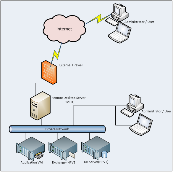
Figure 4: GPC-POC Network Overview
In addition, the physical management server(s) and the host cluster must both be on the same VLAN such that the virtual SCVMM and AD Servers can manage the host cluster and new virtual machines can be provisioned to it.
- Network Architecture
The Hyper-V servers within the environment will be connected to a number of different networks.
Each of the Cluster servers will be configured with up to 5 Networks:
- Management Network
- Virtual Machine Network
- Potentially an ISCSI network (if using an ISCSI SAN)
Optional
- Cluster Heartbeat network
- Live Migration Network (may be shared with Cluster Heartbeat Network if needed)
The Management connection is dedicated to the host itself for network I/O and management.
Optional:
- The Cluster heartbeat connection is used by all the cluster nodes to ascertain if all nodes within the cluster are responding and operational.
- The Live migration network is used to failover virtual machines to alternate nodes in the cluster configuration with no loss of service to the end user.
The Virtual Machine network is dedicated to the guest virtual machines.
The ISCSI Network is used for connection to the ISCSI SAN (if used).
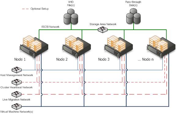
Figure 5: Cluster Node Network Overview
- Storage
The Storage design can be kept as simple as possible – either a FC/ISCSI connection is needed and enough disk space to cater for the potential number of virtual machines is required for the host cluster.
- Backup and Restore
As this is purely a , Virtual machines will not be backed up.
- Security Considerations
- End User Access to the solution
Access to the solution for end-users is via RDP / UAG. It is assumed that the hosting environment is deployed in a secure lab, behind an external Firewall (to the GPC-POC servers).
- RDP Gateway Server: - Remote Desktop Gateway (RD Gateway), formerly Terminal Services Gateway (TS Gateway), is a role service in the Remote Desktop Services server role included with Windows Server® 2008 R2 that enables authorized remote users to connect to resources on an internal corporate or private network, from any Internet-connected device that can run the Remote Desktop Connection (RDC) client. The network resources can be Remote Desktop Session Host (RD Session Host) servers, RD Session Host servers running RemoteApp programs, or computers and virtual desktops with Remote Desktop enabled. RD Gateway uses the Remote Desktop Protocol (RDP) over HTTPS to establish a secure, encrypted connection between remote users on the Internet and internal network resources.
For more reference please see
http://technet.microsoft.com/en-us/library/dd560672(WS.10).aspx
- Unified Access Gateway - Forefront Unified Access Gateway (UAG) allows you to provide access to published RemoteApps and Remote Desktops, by integrating a Remote Desktop Gateway (RD Gateway) to provide an application-level gateway for RDS services and applications. Previously, RDS was published by tunneling Remote Desktop Protocol (RDP) traffic from the endpoint to RDS servers using the Socket Forwarding component; tunneled traffic was not controlled or inspected, and client endpoints required installation of the Socket Forwarding endpoint component.Note: As this is a pure solution, the security of the environment will need to be reviewed against the requirements of the environment into which it is being deployed and as such firewall rules and further security lockdown measures may be required.
For more reference please see
http://technet.microsoft.com/en-us/library/dd857385.aspx
- Host Operating System Configuration
- Keep the management operating system up to date with the latest security updates.
- Use a separate network with a dedicated network adapter for the management operating system of the physical Hyper-V computer.
- Secure the storage devices where you keep virtual machine resource files.
- Harden the management operating system using the baseline security setting recommendations described in the Windows Server 2008 R2 Security Compliance Management Toolkit.
- Configure any real-time scanning antivirus software components installed on the management operating system to exclude Hyper-V resources.
- Do not use the management operating system to run applications.
- Do not grant virtual machine administrators permission on the management operating system.
- Use the security level of your virtual machines to determine the security level of your management operating system.
- Deploying GPC-POC
- Redmond Workflow
- Build iSCSI Target host
- Build 2008 R2 Data Center Hyper-v hosts
- Create Virtual Switches with Hyper-V Manager
Virtual Switch Name | Type | NIC | Network | Physical Swtich | Connectivity |
Public | External | NIC1 | 10.1.1.x | VLAN1 | Corp or VPN connectivity |
Replication | External | NIC2 | 10.1.2.x | VLAN2 | Lab internal |
Hyper-V Failover Cluster | External | NIC2 | 10.0.0.x | VLAN2 | Lab internal |
Table 7: Virtual Switches
- Connect iSCSI volume to the Hyper-V host that will be running the DC1 VM
- Build DC1 VM (...or physical host)
- Copy the Exported Virtual Machine contents of just DC1,
- from external USB drive to a local folder on the Hyper-v host,
- such as C:\GPC Lab\Exported Virtual Machines
- (you can skip this if you want to save time...use Hyper-v Mgr to import directly from USB drive)
- Hyper-v Manager import of DC1 VM from the local C: drive
- (or if you want to save some time, from the USB drive)
- Just make sure that the DC1 VM is imported to a local directory on the Hyper-v host
- Configure contoso.gov
- Install Failover Clustering Feature on hosts
- User Hyper-v Manager to create virtual switch for Clustering, on all hosts
- Use the Failover Cluster Manager MMC snap-in to
- Create a hyper-v cluster with the physical hosts
- Enable CSV
- Create a CSV disk
- Copy
- Build SCVMM & SQL VM
- iSCSI Initiator
- Connect to E: drive
- Install SQL
- Install SCVMM
- Create another CSV disk for the SCVMM Library
- ***due to a storage issue, we were not able to get all the ISO images copied to the external USB drive, so you will need to copy them to this CSV disk
- Create Exchange Template
- Create CAS/HT Template
- Create DC Template
- Create Client Templates
- Use SCVMM or Hyper-v Manager to import remaining VMs onto the appropriate hosts
- Spread the 3 MBX VMs across the HPV hosts, and DO NOT enable Live Migration for these VMs
- Spread the remaining VMs across the HPV hosts with Live Migration enabled
- Customer Workflow
Base OS Server Name | Assigned Machine | Bits | RAM | CPU | Disks | Virtual Switch "Public" | Virtual Switch "Hyper-V & Exchange Replication" | Availability Date | Purpose |
HPB1 | HP Blade 1 | x64 | 64 GB | Quad Core | 2 X 150 GB (300 GB) | Gigabit Ethernet External NIC1 10.1.1.x VLAN1 Corp or VPN | Gigabit Ethernet External NIC2 10.1.2.x VLAN2 Lab internal | Now | Hyper-V (cluster) DDC (SQL, DIT-SC, SCCM, SCOM, SCVMM + Library) Exchange CAS + Hub |
HPB2 | HP Blade 2 | x64 | 64 GB | Quad Core | 2 X 150 GB (300 GB) | Gigabit Ethernet External NIC1 10.1.1.x VLAN1 Corp or VPN | Gigabit Ethernet External NIC2 10.1.2.x VLAN2 Lab internal | Now | Hyper-V failover for HPV1 |
HPB3 | HP Blade 3 | x64 | 32 GB | Quad Core | 2 X 150 GB (300 GB) | Gigabit Ethernet External NIC1 10.1.1.x VLAN1 Corp or VPN | Gigabit Ethernet External NIC2 10.1.2.x VLAN2 Lab internal | Now | Hyper-V (cluster) DAS (273GB - RAID5) Exchange DAG |
HPB4 | HP Blade 4 | x64 | 32 GB | Quad Core | 2 X 150 GB (300 GB) | Gigabit Ethernet External NIC1 10.1.1.x VLAN1 Corp or VPN | Gigabit Ethernet External NIC2 10.1.2.x VLAN2 Lab internal | Now | Hyper-V (cluster) DAS (273GB - RAID5) Exchange DAG |
IBMH1 | IBM 3850 + 2 Fusion IO cards | x64 | 16 GB | Quad Core Intel Xeon Series 7400 | 2 X 650 GB Fusion IO | Gigabit Ethernet External NIC1 10.1.1.x VLAN1 Corp or VPN | N/A | June 16 for Fusion IO cards | iSCSI |
IBMH2 | IBM 3850 | x64 | 12 GB | Quad Core Intel Xeon Series 7400 |
| Gigabit Ethernet External NIC1 10.1.1.x VLAN1 Corp or VPN | N/A | Now | Hyper-V Dual NIC gateway host for remote access May host AD+DNS if Lenovo is not available |
LENH1 | Lenovo RD210 | x64 | 8 GB |
|
| Gigabit Ethernet External NIC1 10.1.1.x VLAN1 Corp or VPN | N/A | June 16 or later | AD+DNS |
Table 8: Hardware Configuration
For more details on the Lab configuration, please refer the Excel sheet attached in the Appendix N
- Passwords
Domain | User Account | Password |
Scvmm-sql-1 | Local Administrator | 1DDCgpclab |
Dc1 | Domain Administrator | 1GPClab |
| Domain Labadmin | 1GPCcontoso |
Hpv5 | Local Administrator | 1GPCcontoso |
Sccm-scom1 | Local Administrator | 1GPCcontoso |
DC3 | OPS Administrator | 1GPClab 1GPCcontoso |
CAS1 |
|
|
Domain | User Account | Password |
CONTOSO | Clusteradmin | 1GPCcontoso |
Table 9: Passwords
Figure 6: - Removed by purpose. Please create the User Accounts as per the above Table 10
Figure 7: Removed by purpose. Please create the User Accounts as per the above Table 10
- iSCSI Target Host Setup
- Install iSCSI target software on designated host
Figure 6: iSCSI Software Setup-1
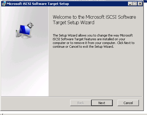
Figure 7: iSCSI Software Setup-2
- Right click on iSCSI Target and select "Create an iSCSI Target"
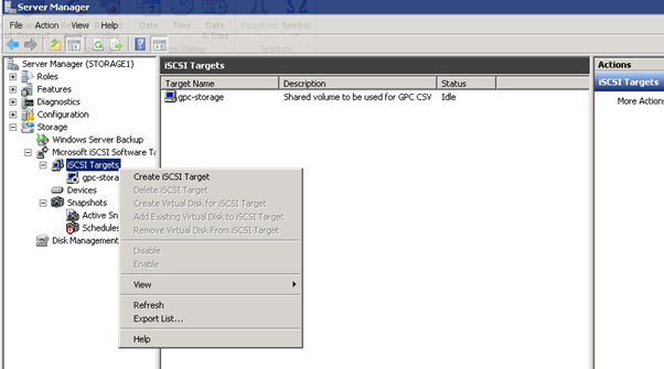
Figure 8: iSCSI Software Setup-3
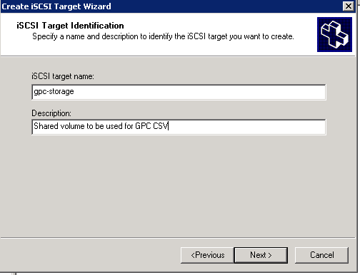
Figure 9: iSCSI Software Setup-4
- Get the IQN of the Hyper-v host that will initially build the contents of the iSCSI volume, which will later be used for the Cluster Shared Volume
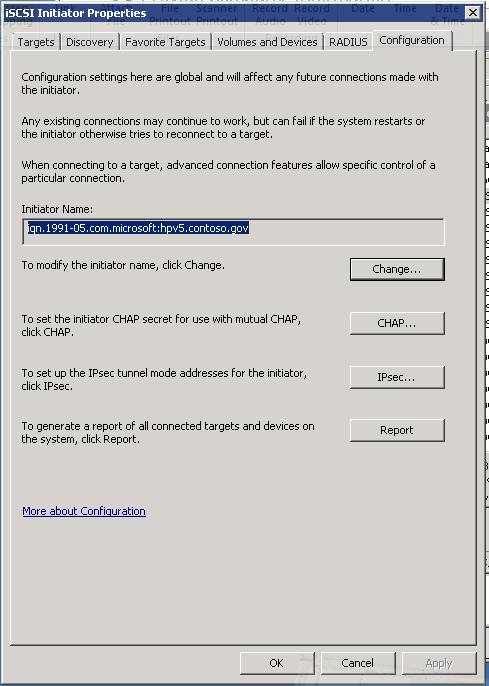
Figure 10: iSCSI Software Setup-5
- On the iSCSI Target Host, paste the IQN identifier of the Hyper-v hosts that we will use to offload the contents of the external USB drive
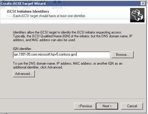
Figure 11: iSCSI Software Setup-6
Figure 12: iSCSI Software Setup-7
- Create virtual disk for iSCSI target, Right click on gpc-storage or select from Actions pane on the right and Select "Create Virtual Disk for iSCSI Target"
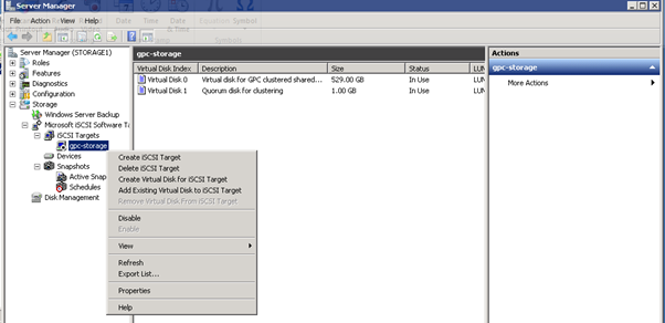
Figure 13: iSCSI Software Setup-8
- Or you can select "Devices", Right click, and select "Create Virtual Disk"
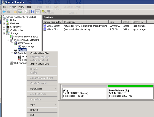
Figure 14: iSCSI Software Setup-9
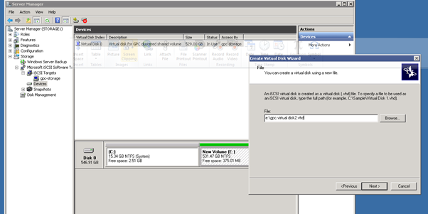
Figure 15: iSCSI Software Setup-10
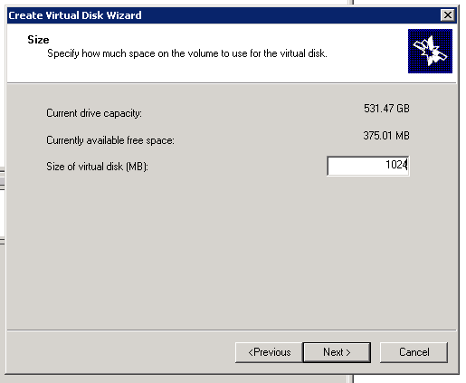
Figure 16: iSCSI Software Setup-11
- This is a 1GB quorum disk for clustering
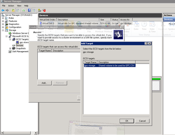
Figure 17: iSCSI Software Setup-12
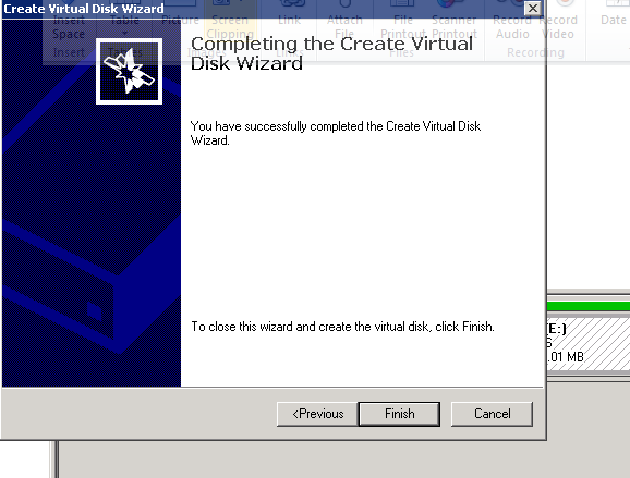
Figure 18: iSCSI Software Setup-13
- Build R2 Hyper-V Core hosts

Figure 19: Build R2 Hyper-V Core hosts - 1
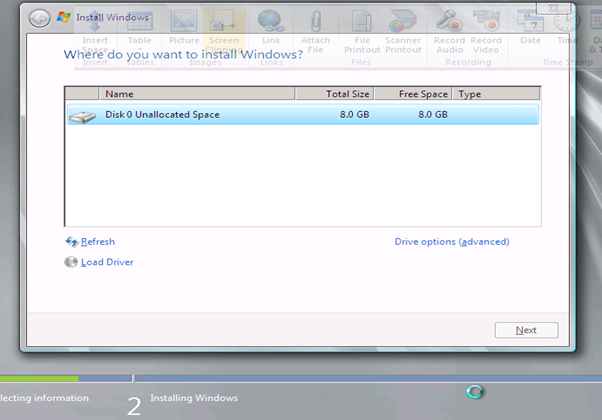
Figure 20: Build R2 Hyper-V Core hosts - 2
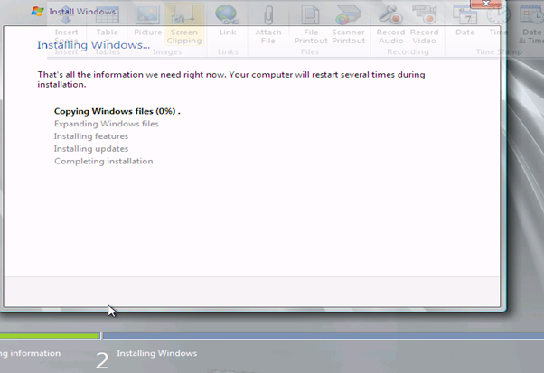
Figure 21: Build R2 Hyper-V Core hosts - 3
- iSCSI Client Setup
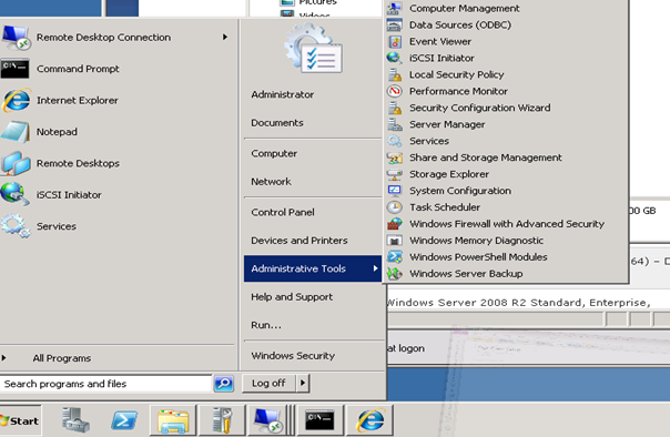
Figure 22: iSCSI Client Setup - 1
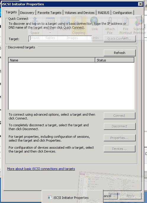
Figure 23: iSCSI Client Setup - 2
- Copy the IQN of the client VM or host, which will be pasted into the iSCSI Target host configuration
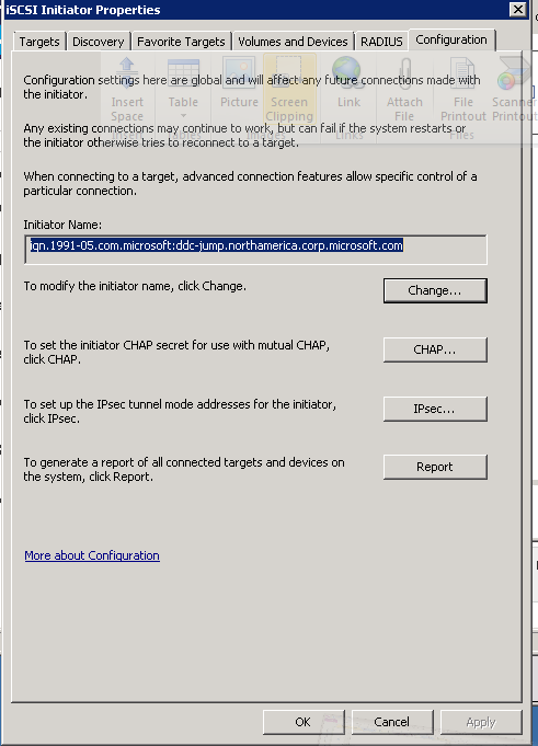
Figure 24: iSCSI Client Setup - 3
- Log into the iSCSI target host
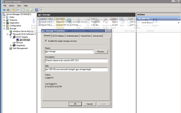
Figure 25: iSCSI Client Setup - 4
- Go to the "Advanced" tab, and paste in the IQN of the Client VM or host
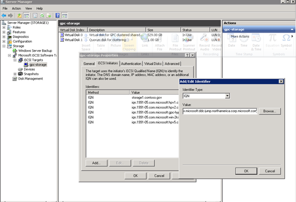
Figure 26: iSCSI Client Setup - 5
- Go back to the client and run the iSCSI Initiator program again
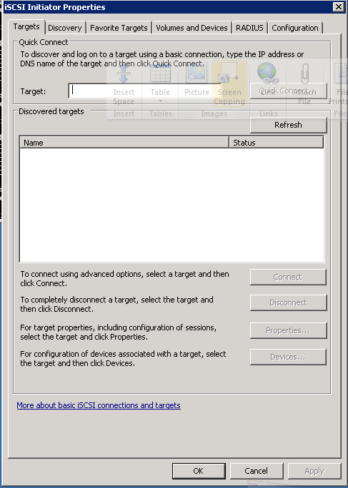
Figure 27: iSCSI Client Setup – 5
- Type in the IP address or FQDN of the iSCSI Target host, and click "Quick Connect"
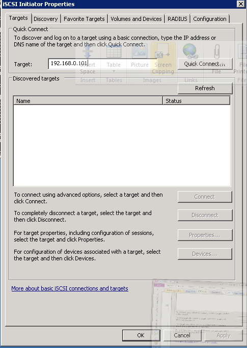
Figure 28: iSCSI Client Setup - 6
- You should see this:
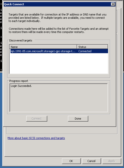
Figure 29: iSCSI Client Setup - 7
- Use the Server Manager tool to navigate to Storage/Disk Management. Find the volume and bring it online, You should see the volume (E: in this case) in the Computer window
- Build DC VMs
- Follow the Hyperv manager steps below to build the DC1 VM
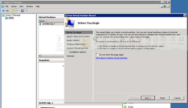
Figure 30: Build DC VMs - 1
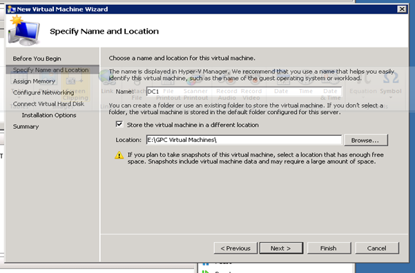
Figure 31: Build DC VMs - 2
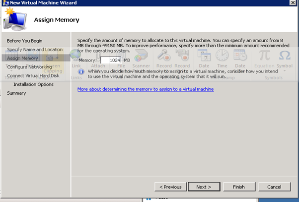
Figure 32: Build DC VMs - 3
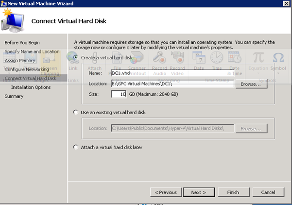
Figure 33: Build DC VMs - 4
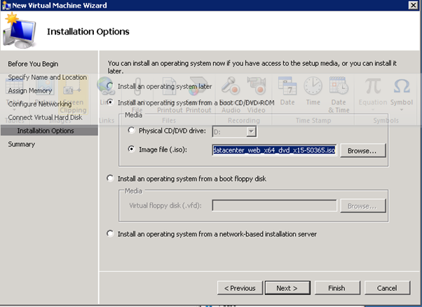
Figure 34: Build DC VMs - 5
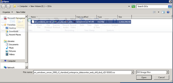
Figure 35: Build DC VMs - 6
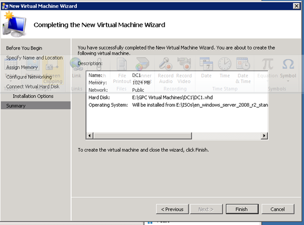
Figure 36: Build DC VMs - 7
- Install Windows Server 2008 R2 Datacenter Edition on all Virtual Machines for this PoC
- Setting up Dcpromo
Set up a Domain Controller on Windows Server 2008.
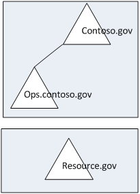
Figure 37.1: Dcpromo - 1
- To use the command, click on Start
 > Run > and then write dcpromo > Click OK
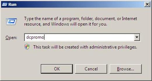
Figure 37.2: Dcpromo - 2
- The system will start checking if Active Directory Domain Services ( AD DS) binaries are installed, then will start installing them. The binaries could be installed if you had run the dcpromo command previously and then canceled the operation after the binaries were installed.
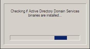
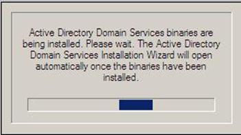
Figure 37.3: Dcpromo - 3
- The Active Directory Domain Services Installation Wizard will start, either enable the checkbox beside Use Advanced mode installation and Click Next , or keep it unselected and click on Next
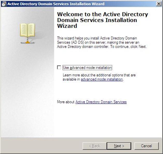
Figure 37.4: Dcpromo - 4
- The following table lists the additional wizard pages that appear for each deployment configuration when you select the Use advanced mode installation check box.
Deployment configuration | Advanced mode installation wizard pages |
New forest | Domain NetBIOS name |
New domain in an existing forest | On the Choose a Deployment Configuration page, the option to create a new domain tree appears only in advanced mode installation. Domain NetBIOS name Source Domain Controller |
Additional domain controller in an existing domain | Install from Media Source Domain Controller Specify Password Replication Policy (for RODC installation only) |
Create an account for a read-only domain controller (RODC) installation | Specify Password Replication Policy |
Attach a server to an account for an RODC installation | Install from Media Source Domain Controller |
- The Operating System Compatibility page will be displayed, take a moment to read it and click Next
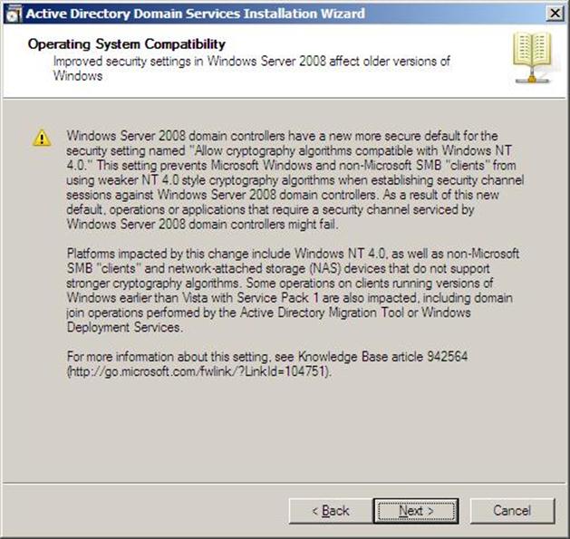
Figure 37.5: Dcpromo - 5
- Choose Create a new domain in a new forest, Click Next
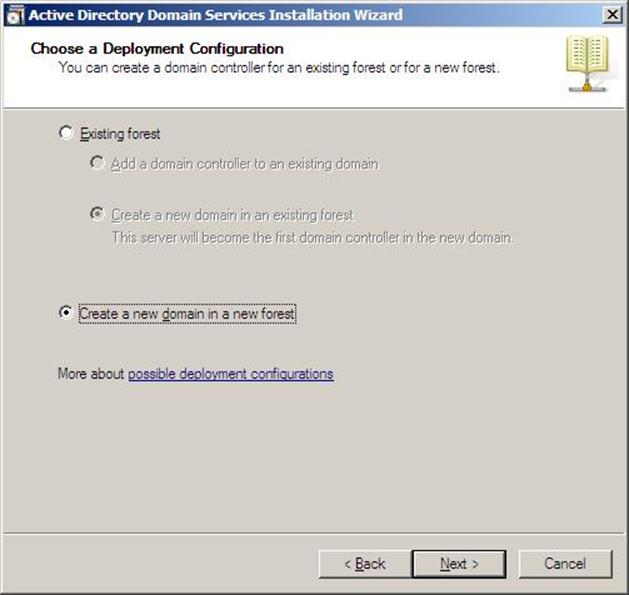
Figure 37.6: Dcpromo - 6
- Enter the Fully Qualified Domain Name of the forest root domain inside the textbox, click Next
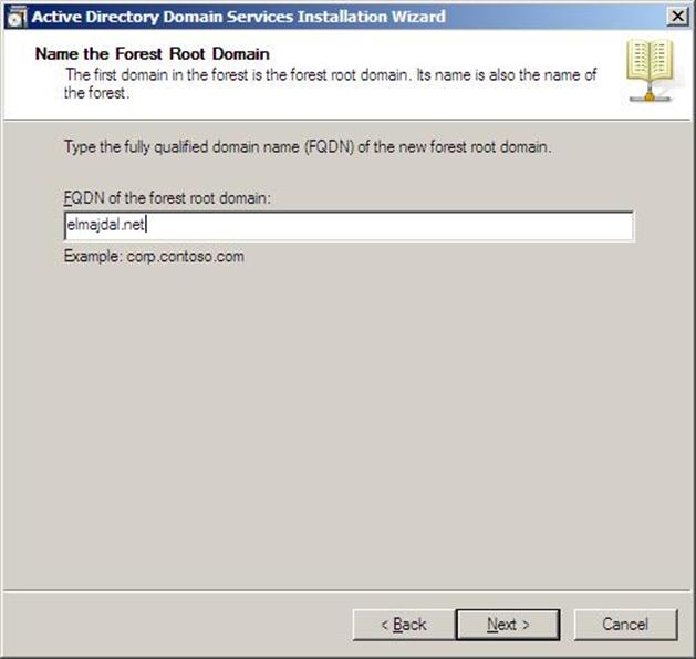
Figure 37.7: Dcpromo - 7
- If you selected Use advanced mode installation on the Welcome page, the Domain NetBIOS Name page appears. On this page, type the NetBIOS name of the domain if necessary or accept the default name and then click Next.
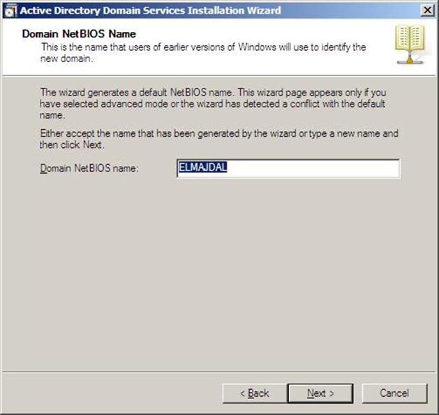
Figure 37.8: Dcpromo - 8
- Select the Forest Functional Level, choose the level you desire and click on Next. Make sure to read the description of each functional level to understand the difference between each one.
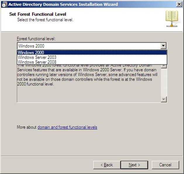
Figure 37.9: Dcpromo - 9
- In the previous step, If you have selected any Forest Functional Level other than Windows Server 2008 and clicked on Next , you would then get a page to select the Domain Functional Level. Select it and then click on Next
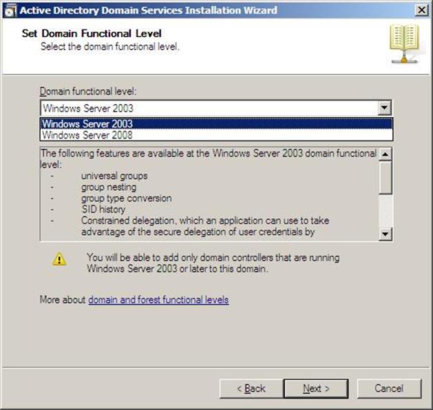
Figure 37.10: Dcpromo - 10
- In the Additional Domain Controller Options page, you can select to install the Domain Name Service to your server. Note that the First domain controller in a forest must be a Global Catalog that's why the checkbox beside Global Catalog is selected and it cannot be cleared. The checkbox is also selected by default when you install an additional domain controller in an existing domain, however you can clear this checkbox if you do not want the additional domain controller to be a global catalog server. The first domain controller in a new forest or in a new domain can not be a Read Only Domain Controller (RODC), you can later add a RODC but you must have at least one Windows Server 2008 Domain Controller.
I want to set my DC as a DNS Server as well, so I will keep the checkbox beside DNS Server selected and click on Next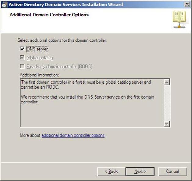
Figure 37.11: Dcpromo - 11
- If the wizard cannot create a delegation for the DNS server, it displays a message to indicate that you can create the delegation manually. To continue, click Yes
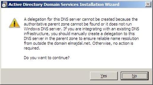
Figure 37.12: Dcpromo - 12
- Now you will have the location where the domain controller database, log files and SYSVOL are stored on the server.
The database stores information about the users, computers and other objects on the network. the log files record activities that are related to AD DS, such information about an object being updated. SYSVOL stores Group Policy objects and scripts. By default, SYSVOL is part of the operating system files in the Windows directory
Either type or browse to the volume and folder where you want to store each, or accept the defaults and click on Next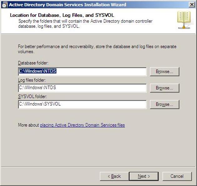
Figure 37.13: Dcpromo - 13
- In the Directory Services Restore Mode Administrator Password (DSRM) page, write a password and confirm it. This password is used when the domain controller is started in Directory Services Restore Mode, which might be because Active Directory Domain Services is not running, or for tasks that must be performed offline.
Make sure that you memorize this password when you need it. I know many administrators forgot it when they most needed it !!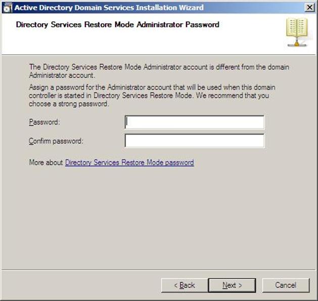
Figure 37.14: Dcpromo - 14 - Make sure the password meet the password complexity requirements of the password policy, that is a password that contains a combination of uppercase and lowercase letters, numbers, and symbols. else you will receive the following message :
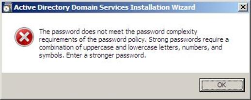
Figure 37.15: Dcpromo - 15
- Summary page will be displayed showing you all the setting that you have set . It gives you the option to export the setting you have setup into an answer file for use with other unattended operations, if you wish to have such file, click on the Export settings button and save the file.
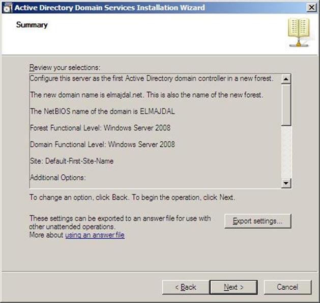
Figure 37.16: Dcpromo - 16
- DNS Installation will start
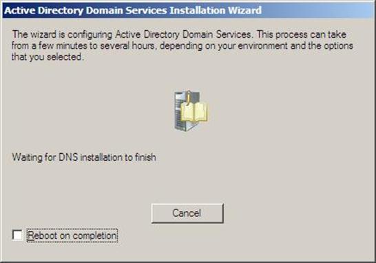
Figure 37.17: Dcpromo - 17
- Followed by installing Group Policy Management Console, the system will check first if it is installed or not.
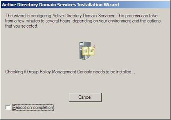
Figure 37.18: Dcpromo - 18
- Configuring the local computer to host active directory Domain Services and other operations will take place setting up this server as a Domain Controller

Figure 37.19: Dcpromo - 19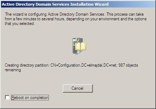
Figure 37.20: Dcpromo - 20
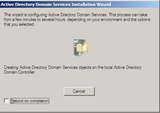
Figure 37.21: Dcpromo - 21
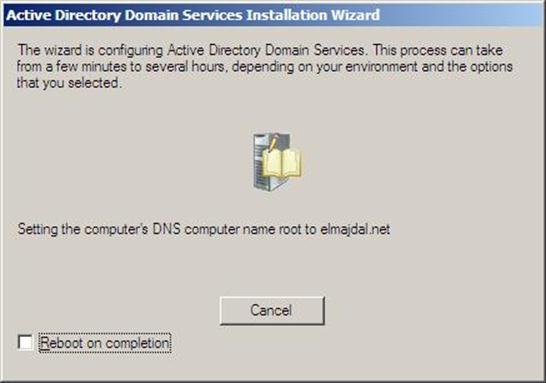
Figure 37.22: Dcpromo - 22
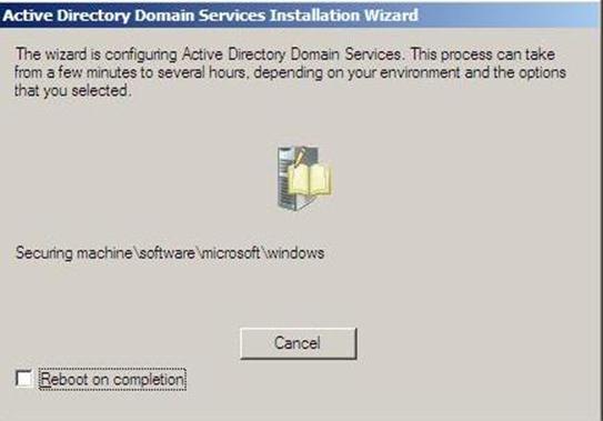
Figure 37.23: Dcpromo - 23
- Active Directory Domain Services installation will be completed, click Finish, then click on Restart Now to restart your server for the changes to take effect.
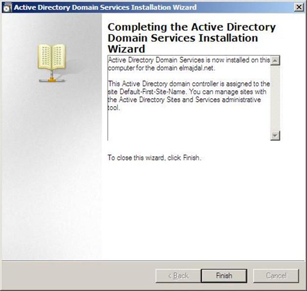
Figure 37.24: Dcpromo - 24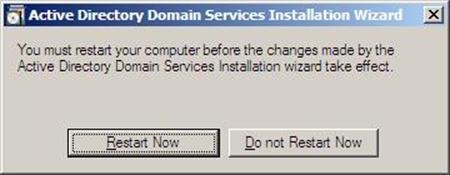
Figure 37.25: Dcpromo - 25
- Once the server is booted and you logon to it, click on Start > Administrative Tools , will notice that following have been installed :
- Active Directory Domains and Trusts
- Active Directory Sites and Services
- Active Directory Users and Computers
- ADSI Edit
- DNS
- Group Policy Management
Figure 37.26: Dcpromo - 26
- Failover Clustering
http://technet.microsoft.com/en-us/library/cc732181(WS.10).aspx#BKMK_Install
- Starting with HPV5
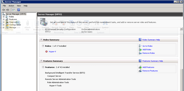
Figure 38: Failover Clustering- 1
- Notice Features Summary does not have Failover Clustering
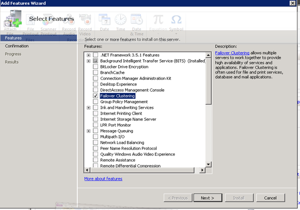
Figure 39: Failover Clustering- 2
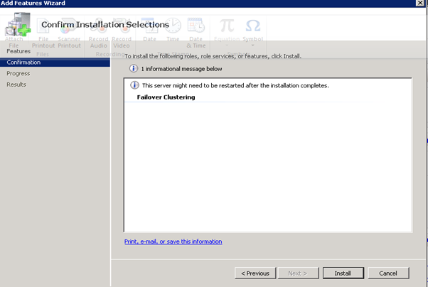
Figure 40: Failover Clustering- 3
- Starting the cluster configuration with HPV3, First need to create a virtual network switch with External connectivity to the 10.0.0.x network
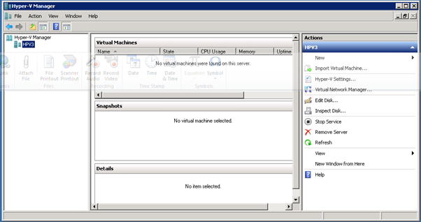
Figure 41: Failover Clustering- 4
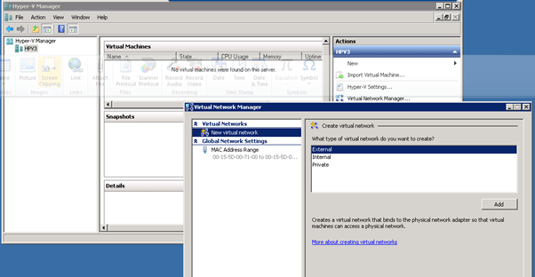
Figure 42: Failover Clustering- 5
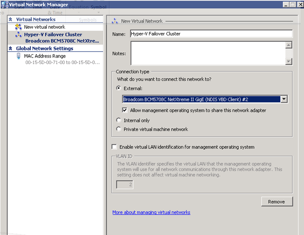
Figure 43: Failover Clustering- 6
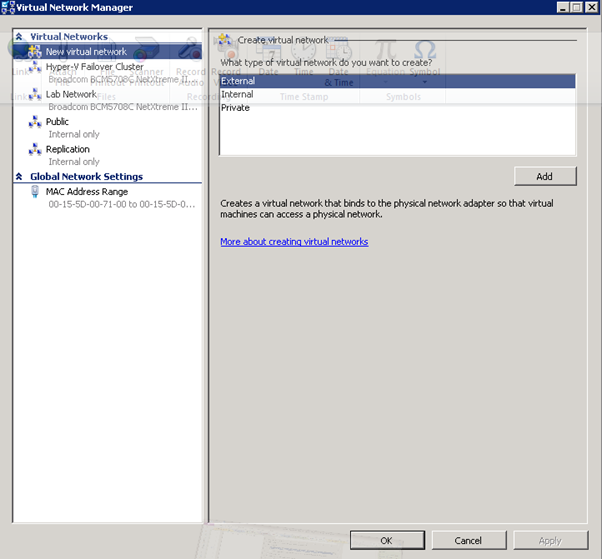
Figure 44: Failover Clustering- 7
- Build SCVMM & SQL VM
Recommended: 4 GB RAM, 2 cores, 40 GB HDD
http://technet.microsoft.com/en-us/library/cc764289.aspx
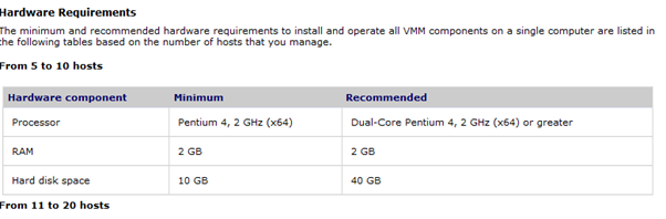
Figure 45: Build SCVMM & SQL VM- 1
System Requirements: Installing VMM on a Single Computer
http://technet.microsoft.com/en-us/library/cc764289.aspx
Figure 46: Build SCVMM & SQL VM- 2
Figure 47: Build SCVMM & SQL VM- 3
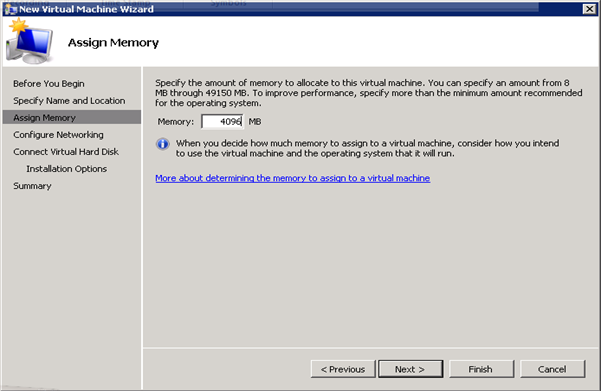
Figure 48: Build SCVMM & SQL VM- 4
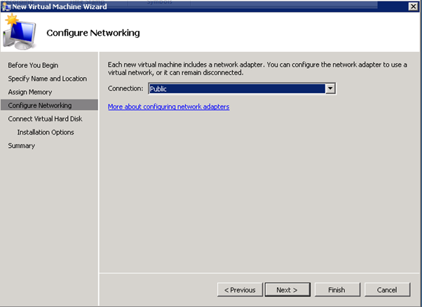
Figure 49: Build SCVMM & SQL VM- 5
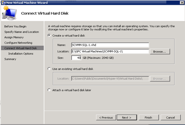
Figure 50: Build SCVMM & SQL VM- 6
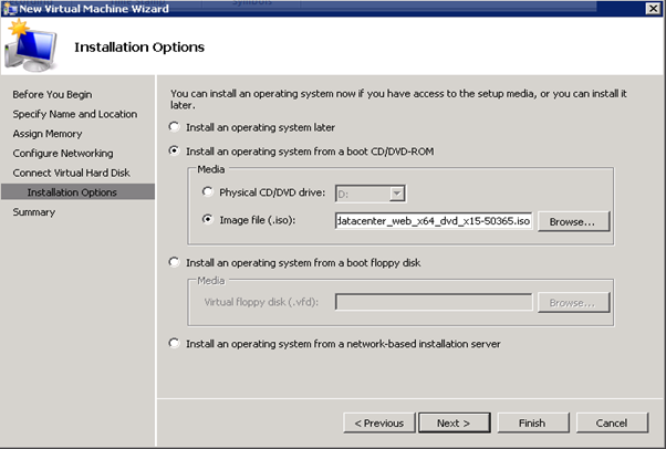
Figure 51: Build SCVMM & SQL VM- 7
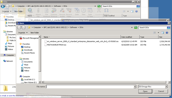
Figure 52: Build SCVMM & SQL VM- 8
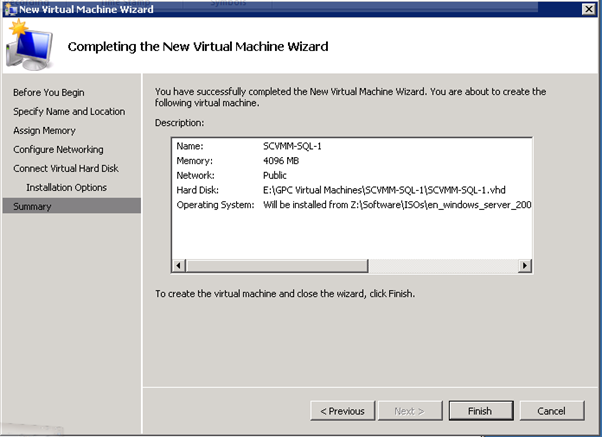
Figure 53: Build SCVMM & SQL VM- 9
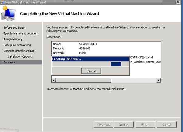
Figure 54: Build SCVMM & SQL VM- 10
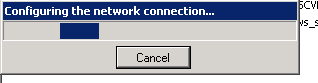
Figure 55: Build SCVMM & SQL VM- 11
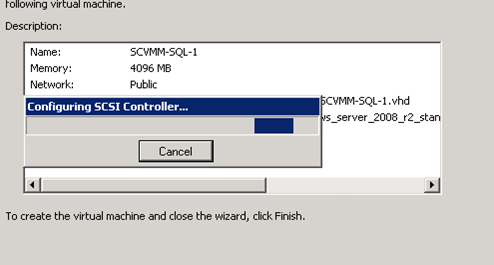
Figure 56: Build SCVMM & SQL VM- 12
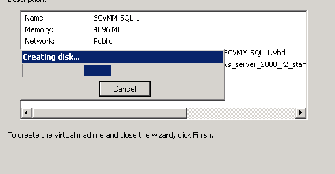
Figure 57: Build SCVMM & SQL VM- 13
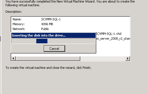
Figure 58: Build SCVMM & SQL VM- 14
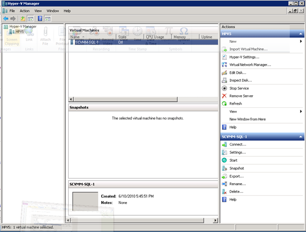
Figure 59: Build SCVMM & SQL VM- 15
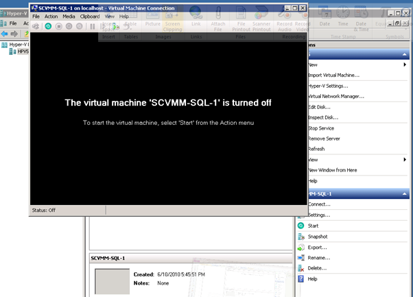
Figure 60: Build SCVMM & SQL VM- 16
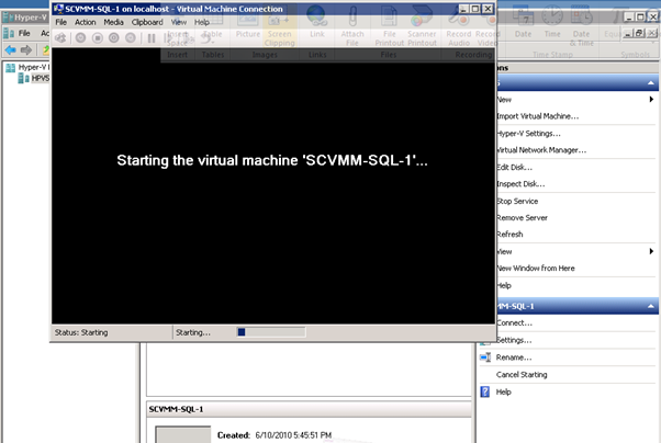
Figure 61: Build SCVMM & SQL VM- 17
- SQL 2008 Install
http://technet.microsoft.com/en-us/library/bb500469(SQL.100).aspx
http://technet.microsoft.com/en-us/library/ms143506(SQL.100).aspx
Installed SQL 2008 Enterprise:
- Copy all of the SQL Server 2008 Enterprise bits from \\products ( you can get it from MSDN as well)
- You will need to install .Net Framework 3.5 via Role Manager prior to installing SQL:
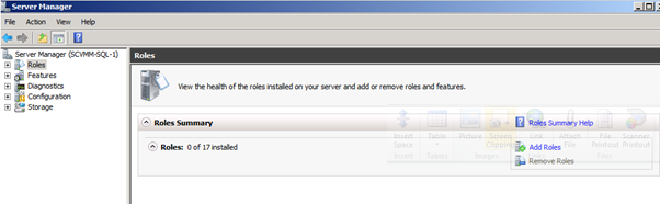
Figure 62: SQL 2008 Install – 1
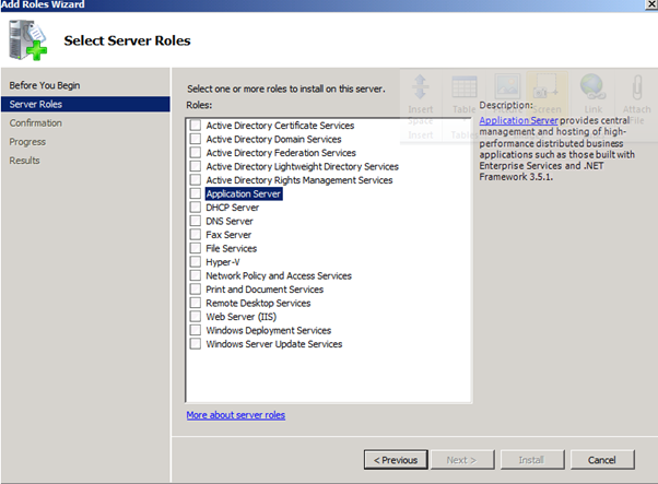
Figure 63: SQL 2008 Install – 2
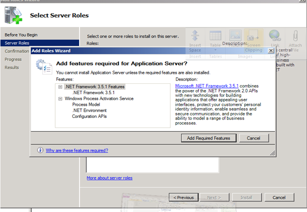
Figure 64: SQL 2008 Install – 3
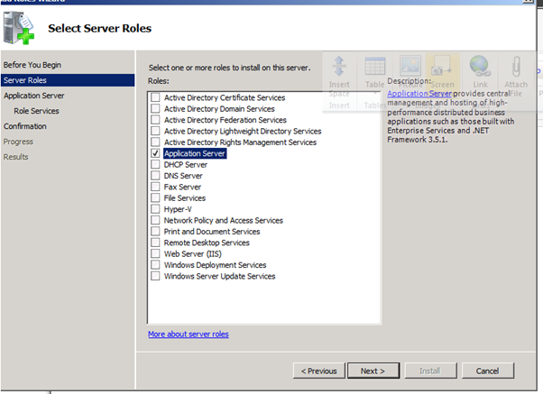
Figure 65: SQL 2008 Install – 4
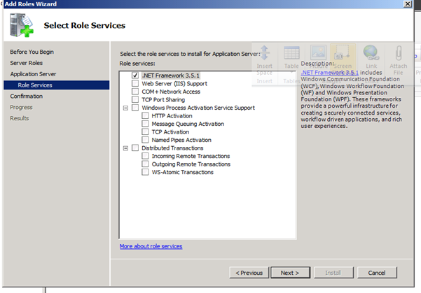
Figure 66: SQL 2008 Install – 5
- Might as well install the "Web Server (IIS) Support", since it will be needed for the other management tools:
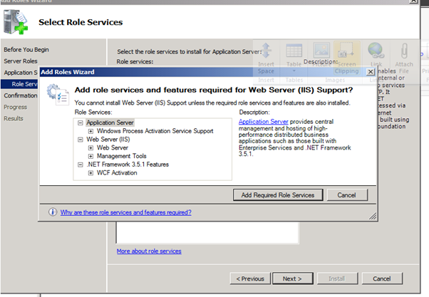
Figure 67: SQL 2008 Install – 6
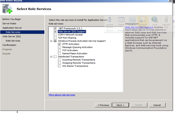
Figure 68: SQL 2008 Install – 7
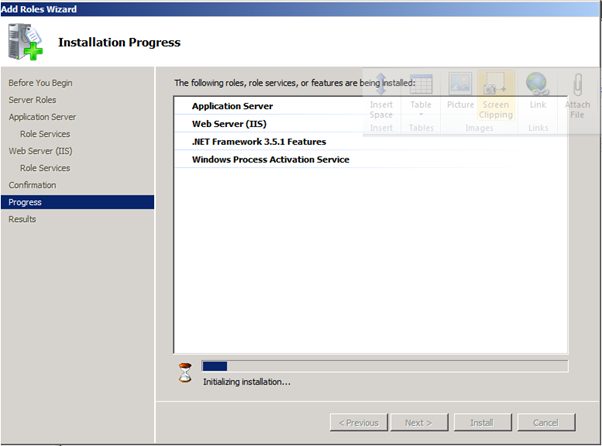
Figure 69: SQL 2008 Install – 8
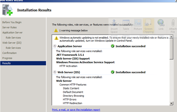
Figure 70: SQL 2008 Install – 9
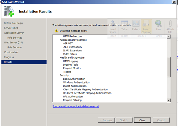
Figure 71: SQL 2008 Install – 10
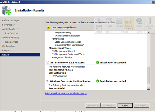
Figure 72: SQL 2008 Install – 11
Figure 73: SQL 2008 Install – 12
- Run the SQL setup:
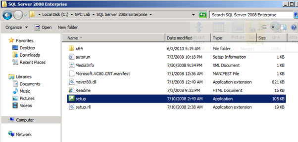
Figure 74: SQL 2008 Install – 13
- It may take a couple of minutes, but you will eventually get the SQL install wizard:
- Click on "Installation"
- Click on "New SQL Server stand-alone installation or add features to an existing installation"
Figure 75: SQL 2008 Install – 14
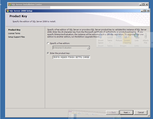
Figure 76: SQL 2008 Install – 15
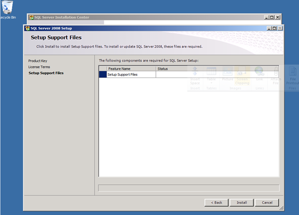
Figure 77: SQL 2008 Install – 16
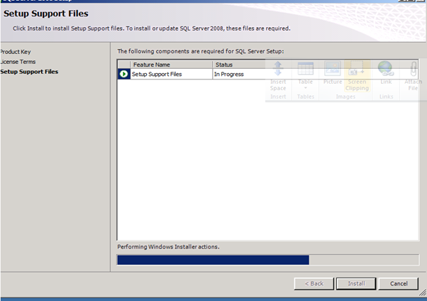
Figure 78: SQL 2008 Install – 17
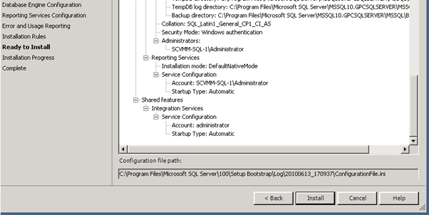
Figure 79: SQL 2008 Install – 18
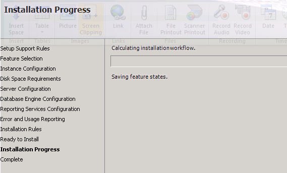
Figure 80: SQL 2008 Install – 19
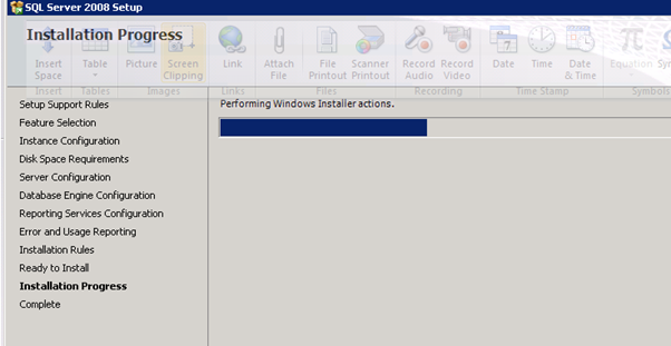
Figure 81: SQL 2008 Install – 20
Below is the screenshots and instructions for getting SCVMM up and running. My installation was performed in a lab environment with Widows 2008 Server R2 providing the Hyper-V functionality so that the hypervisor can have access to the virtualisation extensions of the processor (i.e. hyper-v will work). I've then created two virtual machines, scvmmdc as a domain controller and scvmm to run SCVMM and control hyper-v on machine as a host. True, it's now what you would expect to see in production but it does give you an idea of how to install the software.
The first thing you will note is that I'm not installing a full install to a clustered sql server and, equally, I have not clustered SCVMM to make it highly available both of these things being best practice for a full multi host production environment. You can, of course, get away without doing either of these things in production as you can still control clustered hyper-v from the built in server administration tools, it's just that you won't have access to SCVMM if your single server is not up and running. So, the more physical hosts you have, the "better" practice it is to provide high availability for SCVMM.
The first thing to note after installing the setup disk is that the very first link gives you access to the SCVMM help file which gives excellent advice as to sizing the solution, supported SQL, required software etc (the Setup Overview link).
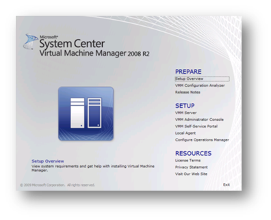
Figure 82: Prepare to Install Screen
Straight from that guide, the software requirements are:
Software requirement | Notes |
A supported operating system | For more information, (generally 2003 SP2 and later). |
Windows Remote Management (WinRM) | This software is included in Windows Server 2008 and the WinRM service is set to start automatically. If the WinRM service is stopped, the Setup Wizard starts the service. |
Microsoft .NET Framework 3.0 | This software is included in Windows Server 2008. If this software has been removed, the Setup Wizard automatically adds it (i.e. no need to download unless you want the latest version – always patch afterwards though). |
Windows Automated Installation Kit (WAIK) 1.1 | If this software has not been installed previously, the Setup Wizard automatically installs it (i.e. no need to download unless you want the latest version – always patch afterwards though). |
Table 2: Software Requirements
If you use the same computer for your VMM server and your VMM database, you must install a supported version of Microsoft SQL Server.
Supported versions of SQL are
- SQL Server 2008 Express Edition
- SQL Server 2008 (32-bit and 64-bit) Standard Edition
- SQL Server 2008 (32-bit and 64-bit) Enterprise Edition
- SQL Server 2005 Express Edition SP2
- SQL Server 2005 (32-bit and 64-bit) Standard Edition SP2
- SQL Server 2005 (32-bit and 64-bit) Enterprise Edition SP2
If you do not specify a local or remote instance of SQL then the Setup Wizard will install SQL Server 2005 Express Edition SP2 on the local computer. The Setup Wizard also installs SQL Server 2005 Tools and creates a SQL Server instance named MICROSOFT$VMM$ on the local computer. To use SQL Server 2008 for the VMM database, SQL Server Management Tools must be installed on the VMM server. If you use Express Edition then SCVMM will not allow reporting and the database size is limited to 4GB.
After reading the pre-requisites we can prepare the server and domain to host SCVMM. The domain needs to be at Windows 2003 domain level as a minimum. Equally, if the SCVMM server is to host the self service portal then IIS needs to be installed and configured. For Windows 2003 this is a simple matter of installing the Application Server role. For Windows 2008 and above add the Web Server (IIS) role and ensure the following role services are selected:
- Static Content
- Default Document
- Directory Browsing
- HTTP Errors
- ASP.NET
- .Net Extensibility
- ISAPI Extensions
- ISAPI Filters
- Request Filtering
- IIS 6 Metabase Compatibility
- IIS 6 WMI Compatibility
We can then check the server for suitability for hosting SCVMM. This can be done locally or form a remote machine but whichever machine is being used for this task, that machine needs to have the Microsoft Baseline Configuration Analyzer installed which can be downloaded from http://go.microsoft.com/fwlink/?LinkId=97952. Once the MBCA has been installed we can then click the link for the VMM Configuration Analyzer. This will allow you to download the analyzer tool to your local machine and pre-check the machine for suitability for hosting SCVMM.
When starting the Analyzer tool from the start menu we have the following choices (SCVMM is the name of my lab machine). The tool should really be run in the context of an account that is a domain administrator in order that the tool can accurately check the domain level.
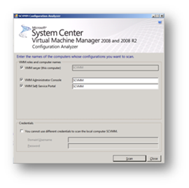
Figure 83: Prepare to Install SCVMM
After clicking Scan and waiting a short while you will be presented with a report for which you will need to correct any errors.
Once all errors are resolved we can move onto installing the SCVMM software. Simply click on "SCVMM Server" under the setup section of the welcome screen. Setup will extract some temporary files and then begin the installation routine. Read and accept the license terms if you agree with them and wish to proceed.
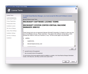
Figure 84: Prepare to Install SCVMM
I recommend that you participate in the customer experience program if you wish to see Microsoft improve their software for you and all other users.
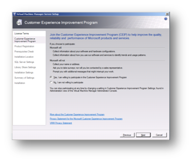
Figure 85: Prepare to Install SCVMM
Complete the User registration details according to your corporate standards.
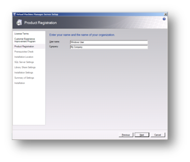
Figure 86: Prepare to Install SCVMM
Complete the prerequisites check and, if passed, click on Next.

Figure 87: Prepare to Install SCVMM
Select where to install the software binaries.
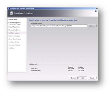
Figure 88: Prepare to Install SCVMM
As I don't have a separate SQL server in my lab I chose to install SQL Express locally on my server.
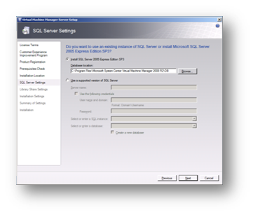
Figure 89: Prepare to Install SCVMM
I created a new folder called "Library" and changed the path for the library share to used that new location. In the normal course of events I would usually put this on a drive other than C to allow for growth.
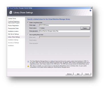
Figure 90: Prepare to Install SCVMM
While it is a best practice to change the port numbers used (one for security and two, because you have to uninstall and reinstall SCVMM if you want to change the ports later) I have left them at their defaults for my lab. Similarly, it is a security best practice to leave the service account as the system account. A network account should be used if SCVMM is being installed in a clustered environment where SCVMM is itself clustered.
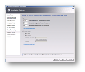
Figure 91: Prepare to Install SCVMM
At the summary of settings page click on Install to proceed.
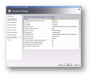
Figure 92: Prepare to Install SCVMM
The software and pre-requisite software will then be installed.
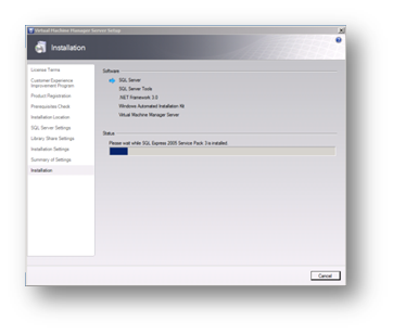
Figure 93: Prepare to Install SCVMM
Finally, once the installation has completed select Close to check for any SCVMM updates.
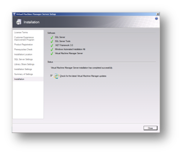
Figure 94: Prepare to Install SCVMM
This will have installed SCVMM server. Next, we need to install the Administrators Console. After any required patching, reboot the server and start setup from the CD once more and select VMM Administrator Console in the setup section. Once again temporary files will be extracted and the installation process will begin. As before, we first read and accept the license agreement if we want to proceed.

Figure 95: Prepare to Install SCVMM
There is no need to join the Customer Experience Improvement Program as this screen will pick up the choice made when installing SCVMM server (this choice is available if installing the administrative console onto an administrators workstation).
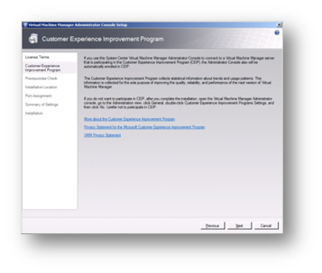
Figure 96: Prepare to Install SCVMM
Complete the prerequisites check and, if passed, click on Next.

Figure 97: Prepare to Install SCVMM
Select the installation location and click on Next.
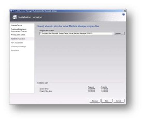
Figure 98: Prepare to Install SCVMM
Next, we assign the port that we want the console to use to communicate with the SCVMM Server. This is the port that you assigned when installing SCVMM Server above. The port setting that you assign for the VMM Administrator Console must identically match the port setting that you assigned for the VMM Administrator Console during the installation of the VMM server or communication will not occur.
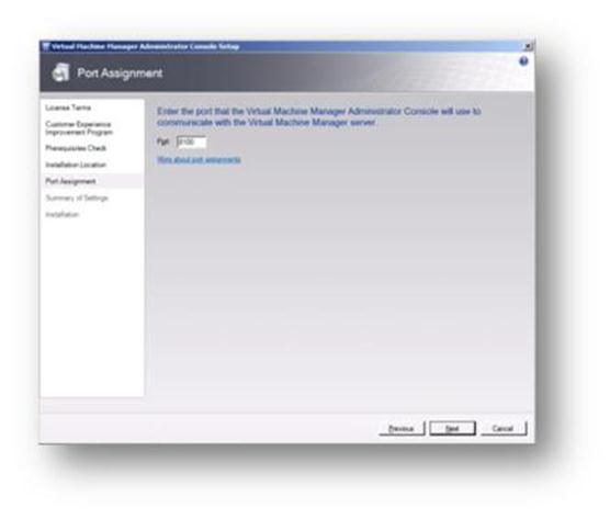
Figure 99: Prepare to Install SCVMM
On the Summary of Settings page, if all settings are fine then click on Install.
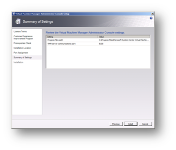
Figure 100: Prepare to Install SCVMM
The installation will then proceed.
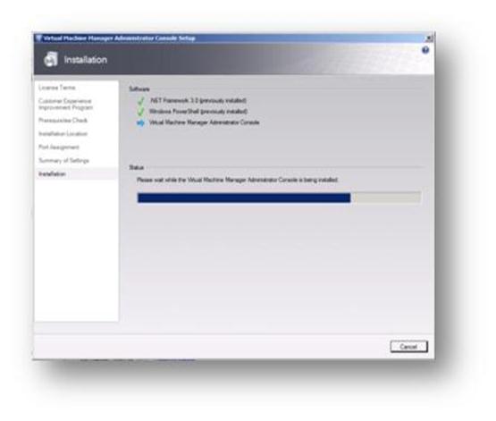
Figure 101: Prepare to Install SCVMM
Once again, click on Close and check for any updates to the software.
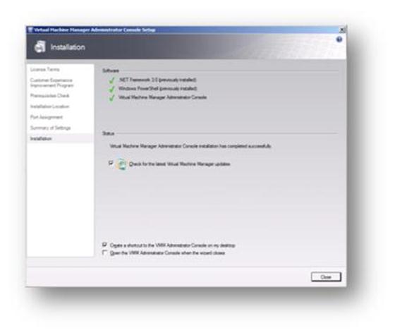
Figure 102: Prepare to Install SCVMM
Once any updates have been installed and the server has been rebooted we can proceed to install the optional VMM Self-Service Portal. The Self Service Portal allows identified users to create and manage virtual machines within a Hyper-V or VMWare environment where SCVMM is managing VMWare hosts. To begin the install simply click on the VMM Self-Service Portal link under the Setup section of the welcome page. Once again temporary files will be extracted and the installation process will begin. As before, we first read and accept the license agreement if we want to proceed.
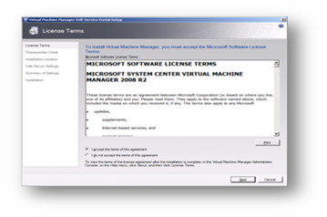
Figure 103: Prepare to Install SCVMM
Complete the prerequisites check and, if passed, click on Next (remember, IIS must have been installed to install this service).
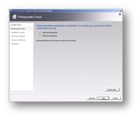
Figure 104: Prepare to Install SCVMM
We can then choose where to install the application binaries. Here, I have chosen the default location for my lab. In a production environment I would move these to a drive other than C.
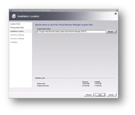
Figure 105: Prepare to Install SCVMM
Next we tell the installation what port we would like users to connect to the self-service portal over. Generally this is port 80 but if another web site is being hosted on the server then we can either select a different port or, more usually, set a different host / web address to be used by the solution by way of host headers. If port 80 is already in use (by the default web site for example) then we receive the error message below.
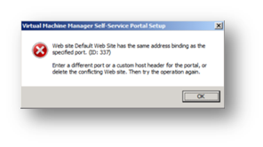
Figure 106: Prepare to Install SCVMM
I've used the hostname selfservice and registered this in my DNS servers as a host (A) record to enable clients to find the site. Additionally, we once again have to connect to our SCVMM server and need to enter the port number chosen earlier for connections. We can then click on Next to move to the next screen.
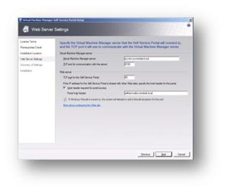
Figure 107: Prepare to Install SCVMM
On the Summary page we can now select Install if we are happy with all of our settings.
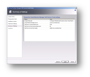
Figure 108: Prepare to Install SCVMM
Once again we click on Close and check for any updates to the software.
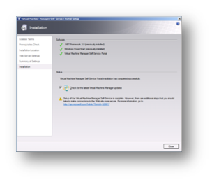
Figure 109: Prepare to Install SCVMM
Once the installation is complete we can once again check for any updates and reboot the server to ensure that all services start cleanly (checking the event log for any issues on startup).
Once restarted you can take time if necessary to harden your self-service portal environment by deploying SSL (to encrypt traffic), using integrated logon (to prevent users having to enter passwords) and disabling unwanted ISAPI filters. The full guide on recommended hardening measures can be found at http://go.microsoft.com/fwlink/?LinkId=123617.
If you have followed these steps you should now have a fully functional SCVMM server which can be connected to your Hyper-V or VMWare servers. Connecting to Hyper-V couldn't be simpler. When you add a virtual machine host or library server that is in an Active Directory domain, SCVMM remotely installs an SCVMM agent on the Hyper-V host. The SCVMM agent deployment process uses both the Server Message Block (SMB) ports and the Remote Procedure Call (RPC) port (TCP 135) and the DCOM port range. You can use either SMB packet signing or IPSec to help secure the agent deployment process. You can also install SCVMM agents locally on hosts, discover them in the SCVMM Administrator Console, and then control the host using only the WinRM port (default port 80) and BITS port (default port 443). Even though we do not need to install the Local Agent manually as all of our servers reside in a domain I run through the procedure for installation below. First we insert the SCVMM disc into our hyper-v server (or map a drive to it) and start the setup routine and then click on Local Agent under setup. The installation of the Local Agent will then begin.
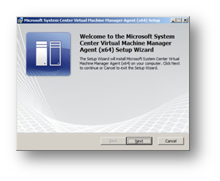
Figure 110: Prepare to Install SCVMM
Accept the terms of the agreement to continue.
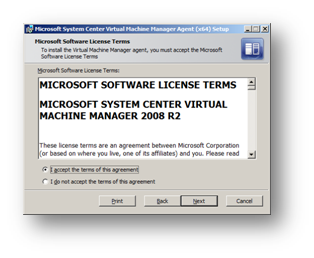
Figure 111: Prepare to Install SCVMM
Select the installation path.
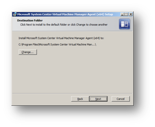
Figure 112: Prepare to Install SCVMM
Change the ports the Hyper-V server will use to connect to the SCVMM server to those set earlier when SCVMM was installed.
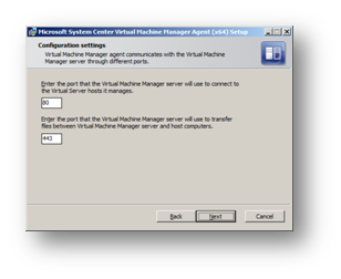
Figure 113: Prepare to Install SCVMM
Our server is not sitting in a DMZ – if it were we could encrypt traffic between the Hyper-V server and SCVMM.
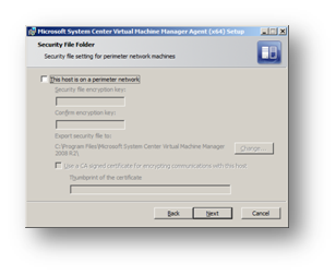
Figure 114: Prepare to Install SCVMM
You can then continue to Install the Agent
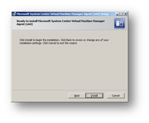
Figure 115: Prepare to Install SCVMM
Click on Finish when completed.
Figure 116: Prepare to Install SCVMM
Next we need to start the SCVMM Admin console on the SCVMM server by double clicking the link created on your desktop or by using the link in the Start menu.
Figure 117: Prepare to Install SCVMM
From the Outlook like interface we can select the Hosts section and from there we can create a new host group if we have a number of physical Hyper-V or VMWare hosts we would like to control. For our purposes we'll just use the All Hosts group. On the right hand side (Actions column) we can select Add Host.
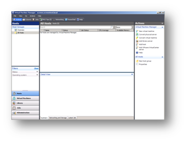
Figure 118: Prepare to Install SCVMM
In my lab the Hyper-V server is part of my domain as it would have to be if we were running a Hyper-V cluster and so we select the first choice and enter the domain administrator credentials to allow SCVMM access to the Hyper-V host.
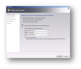
Figure 119: Prepare to Install SCVMM
Next, type in the name of the physical server running Hyper-V or browse for it in Active Directory. Note: Hyper-V does not need to be installed on the host at this point – if it is not then SCVMM will install and activate the role on the target server and reboot it.
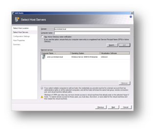
Figure 120: Prepare to Install SCVMM
Add the host machine to a host group.
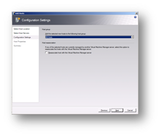
Figure 121: Prepare to Install SCVMM
Add a default path where Virtual Machines should be created on this host. When you add a stand-alone Windows Server-based virtual machine host as we are doing here to Virtual Machine Manager (SCVMM), you can add one or more virtual machine default paths, which are paths to folders where SCVMM can store the files for virtual machines that are deployed on the hosts. However, For a Hyper-V or VMWare cluster the default path is a shared volume on the cluster that SCVMM automatically creates when you add the host cluster. When you are adding the host cluster, you cannot specify additional default paths in the Add Host Wizard.
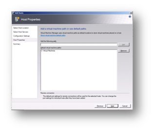
Figure 122: Prepare to Install SCVMM
We then get asked to confirm the settings and can select to add our host.
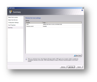
Figure 123: Prepare to Install SCVMM
Once added a job will auto-run to add the host followed by a further series of jobs to add in any already configured Virtual Machines running on that host into SCVMM.

Figure 124: Prepare to Install SCVMM
You should now be able to control your Hyper-V host using SCVMM and configure the self-service portal for your users.
- Individual SCVMM Install
- Log into the SCVMM-SQL-1 virtual machine as:
ops\labadmin
1GPCcontoso
- Software has been copied to the local harddrive
Local Disk (C:) \GPC Lab\Virtual Machine Manager 2008 R2
- Run setup.exe
- Install VMM Server first...
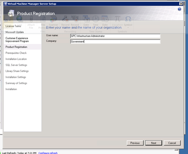
Figure 125: SCVMM Install – 1
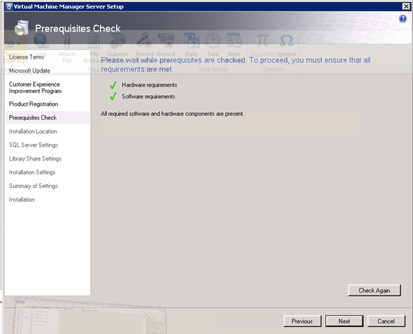
Figure 126: SCVMM Install – 2
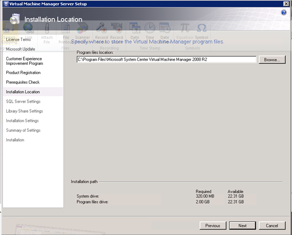
Figure 127: SCVMM Install – 3
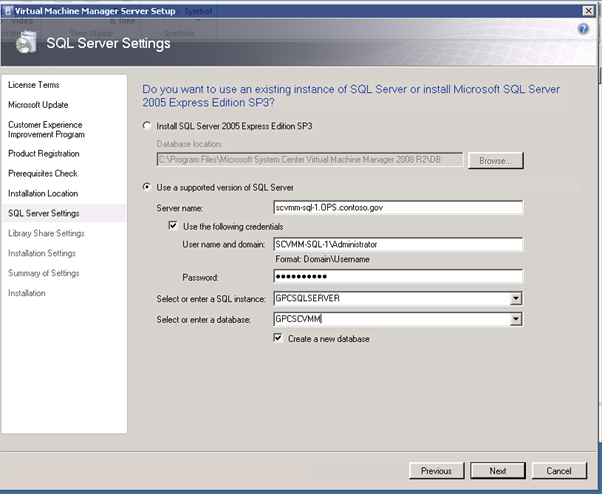
Figure 128: SCVMM Install – 4
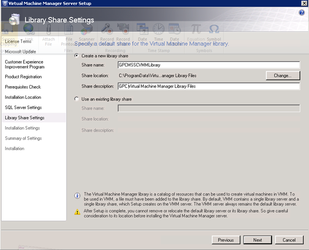
Figure 129: SCVMM Install – 5
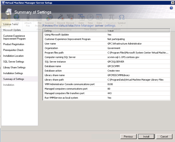
Figure 130: SCVMM Install – 6
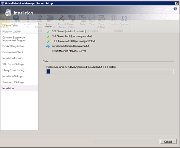
Figure 131: SCVMM Install – 7
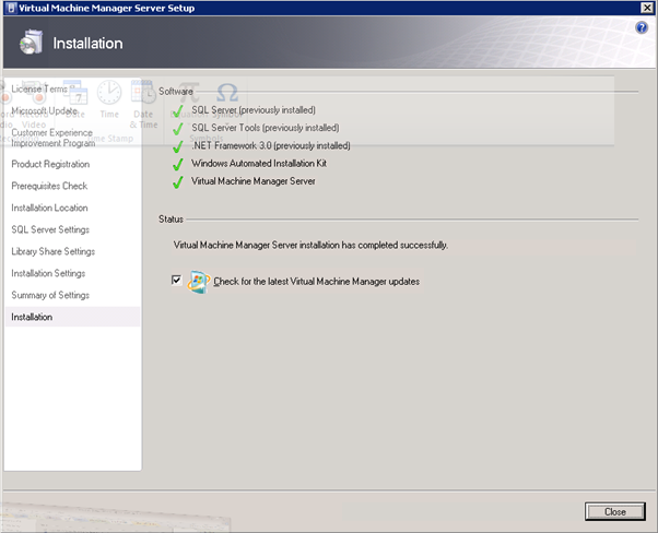
Figure 132: SCVMM Install – 8
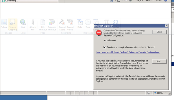
Figure 133: SCVMM Install – 9
Install VMM Administrator Console…..
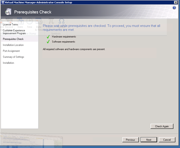
Figure 134: SCVMM Install – 10
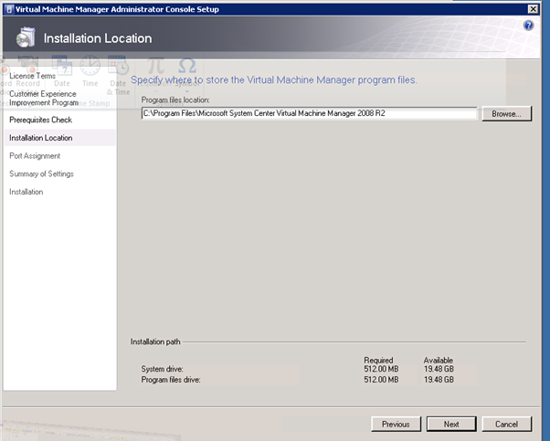
Figure 135: SCVMM Install – 11
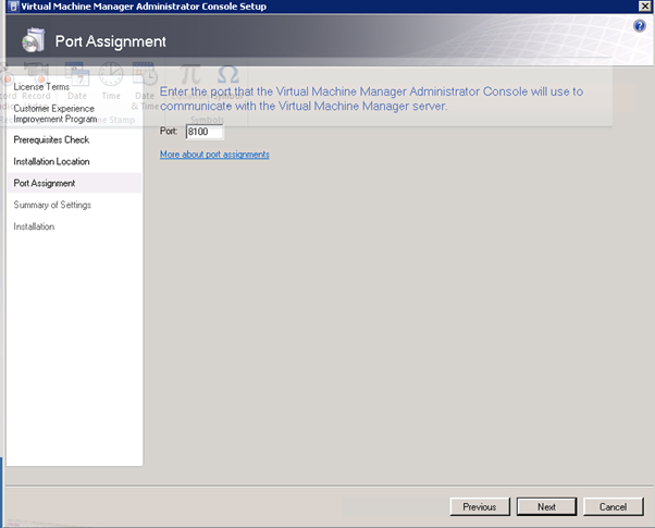
Figure 136: SCVMM Install – 12
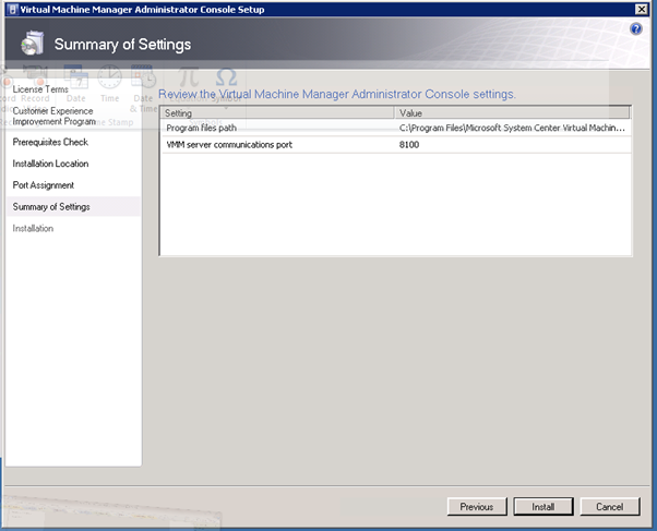
Figure 137: SCVMM Install – 13
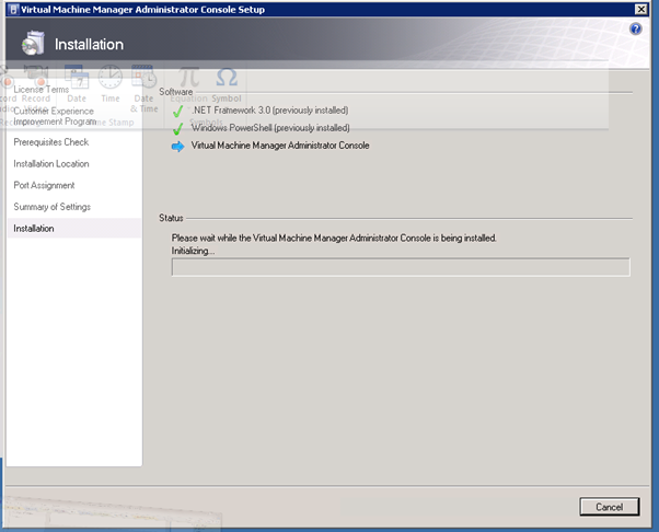
Figure 138: SCVMM Install – 14
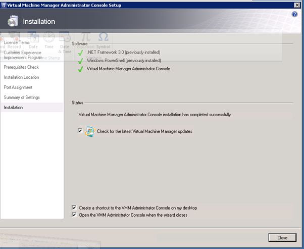
Figure 139: SCVMM Install – 15
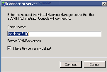
Figure 140: SCVMM Install – 16
Figure 141: SCVMM Install – 17
Figure 142: SCVMM Install – 18
Figure 143: SCVMM Install – 19
Figure 144: SCVMM Install – 20
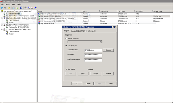
Figure 145: SCVMM Install – 21
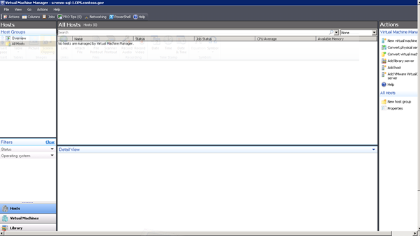
Figure 146: SCVMM Install – 22
Enter E:\GPC Virtual Machines for the default path and Enter the remaining defaults for adding the host
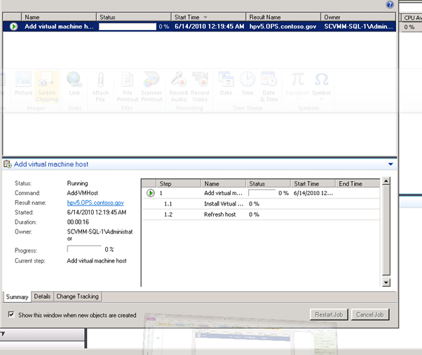
Figure 147: SCVMM Install – 23
- DIT-SC Install
- System Requirements: Single-Machine Deployment Scenario
As described previously, the single-machine deployment scenario requires installing all three VMMSSP components on a computer that is running the VMM Administrator Console and SQL Server 2008.
Hardware Requirements
The following table provides the minimum and recommended hardware requirements for a single–machine deployment.
Table 6. Required Hardware for a Single–Machine Deployment Scenario
Hardware Component | Minimum | Recommended |
RAM | 2 GB | 4 GB |
Available hard disk space | 50 GB | 50 GB |
Software Requirements
Before you install the VMMSSP website component, install and configure the following software on the computer.
Table 7. Required Software for a Single-Machine Deployment Scenario
Software | Comments |
Operating System: Windows Server® 2008 R2 | Windows Server 2008 R2 Enterprise Edition and Windows Server 2008 R2 Datacenter Edition are supported. |
Windows Server Internet Information Services (IIS) 7.0 | You must add the Web server role (IIS) and then install the following role services:
Turn off Anonymous authentication. For more information, see Configure Windows Authentication in the IIS documentation. Use IIS v6.0 compatibility mode. |
Microsoft .NET Framework 3.5 SP1 | Download from Microsoft Download Center: Microsoft .NET Framework 3.5 Service Pack 1 |
Windows PowerShell™ 2.0 | Important If your extensibility scripts require specific Windows PowerShell snap-ins, install them when you install the VMMSSP server component. |
Microsoft Message Queuing (MSMQ) | You must install the Message Queuing Server feature of MSMQ. This feature is the core component of Message Queuing, which enables you to perform basic Message Queuing functions. For more information, see What is Message Queuing? Note In Windows Server 2008 R2, you install and uninstall Message Queuing by using the Add Features Wizard available in Server Manager. |
VMM 2008 R2 Administrator Console | For more information about installing the VMM 2008 R2 Administrator Console, download and read the Virtual Machine Manager Deployment Guide. |
SQL Server 2008 | SQL Server 2008 Enterprise (64-bit) and SQL Server 2008 Standard (64-bit) versions are supported. |
- System Requirements: VMMSSP Website Component
This section lists the hardware and software required for the VMMSSP website component if you install it on a dedicated Web server.
Hardware Requirements
The following table provides the minimum and recommended hardware requirements for the VMMSSP website component.
Table 8. Required Hardware for the VMMSSP Website Component
Hardware Component | Minimum | Recommended |
RAM | 2 GB | 4 GB |
Available hard disk space | 50 MB | 2 GB |
Software Requirements
Before you install the VMMSSP website component, install and configure the following software on the Web server.
Table 9. Required Software for the VMMSSP Website Component
Software | Comments |
Operating System: Windows Server 2008 R2 | Windows Server 2008 R2 Enterprise Edition and Windows Server 2008 R2 Datacenter Edition are supported. |
Windows Server Internet Information Services (IIS) 7.0 | You must add the Web server role (IIS) and then install the following role services:
Turn off Anonymous authentication. For more information, see Configure Windows Authentication in the IIS documentation. Use IIS v6.0 compatibility mode. |
Microsoft .NET Framework 3.5 SP1 | Download from Microsoft Download Center: Microsoft .NET Framework 3.5 Service Pack 1 |
- System Requirements: VMMSSP Server Component
This section lists the hardware and software required for the VMMSSP server component if you install it on a computer that is dedicated to the self-service portal and the VMM Administrator Console.
Hardware Requirements
The following table provides the minimum and recommended hardware requirements for the VMMSSP server component.
Table 10. Required Hardware for the VMMSSP Server Component
Hardware Component | Minimum | Recommended |
RAM | 2 GB | 4 GB |
Available hard disk space | 50 MB | 2 GB |
Software Requirements
Before you install the VMMSSP server component, install and configure the following software on the computer that will run the server component.
Table 11. Required Software for the VMMSSP Server Component
Software | Comments |
Operating System: Windows Server 2008 R2 | Windows Server 2008 R2 Enterprise Edition and Windows Server 2008 R2 Datacenter Edition are supported. |
Microsoft .NET Framework 3.5 SP1 | Download from Microsoft Download Center: Microsoft .NET Framework 3.5 Service Pack 1 |
Windows PowerShell 2.0 | Important If your extensibility scripts require specific Windows PowerShell snap-ins, install the snap-ins with the server component. For information about extending the self-service portal with scripts, see the Virtual Machine Manager 2008 R2 VMMSSP Extensibility Guide. |
Microsoft Message Queuing (MSMQ) | You must install the Message Queuing Server feature of MSMQ. This feature is the core component of Message Queuing, which enables you to perform basic Message Queuing functions. For more information about the Message Queuing Server feature, see What is Message Queuing? Note In Windows Server 2008 R2, you install and uninstall Message Queuing by using the Add Features Wizard available in Server Manager. |
VMM 2008 R2 Administrator Console | Install the VMMSSP server component on a computer that already has the VMM Administrator Console installed. For more information about installing the VMM 2008 R2 Administrator Console, see the Virtual Machine Manager Deployment Guide. |
- System Requirements: VMMSSP Database Component
This section lists the hardware and software required for the VMMSSP database component if you install it on a dedicated SQL Server computer.
Hardware Requirements
The following table provides the minimum and recommended hardware requirements for the VMMSSP database component.
Table 12. Required Hardware for the VMMSSP Database Component
Hardware Component | Minimum | Recommended |
RAM | 2 GB | 4 GB |
Available hard disk space | 50 GB | 50 GB |
Table 13. Required Software for the VMMSSP Database Component
Software | Comments |
Operating System: Windows Server 2008 R2 | Windows Server 2008 R2 Enterprise Edition and Windows Server 2008 R2 Datacenter Edition are supported. |
SQL Server 2008 | SQL Server 2008 Enterprise (64-bit) and SQL Server 2008 Standard (64-bit) versions are supported. |
The Self-Service Portal Setup wizard installs all three of the self-service portal components.
Important Before you can begin using the self-service portal, you must create a service role for self-service portal users in VMM. In the VMM Administrator Console, create a service role named Self Service Role. For more information, see How to Create a Self-Service User Role in the Virtual Machine Manager documentation. The ConnectVM virtual machine action will not work till this step is completed.
Important You must have administrator permissions on the computers on which you intend to install the self-service portal components. You also must be a member of the local Administrators group on the computer running SQL Server.
To install the VMMSSP server component and database component
Note This procedure assumes that you have a separate database server available, running SQL Server 2008 Enterprise Edition or Standard Edition.
- Download the SetupVMMSSP.exe file and place it on each computer on which you want to install self-service portal components.
- To begin the installation process, on the computer on which you are installing the server component, right-click SetupVMMSSP.exe, and then click Run as administrator.
- On the Welcome page, click Install.
- Review and accept the license agreement, and then click Next.
- Click VMMSSP server component, and then click Next.
- On the Check Prerequisites for the Server Component page, wait for the wizard to complete the prerequisite checks, and then review the results. If any of the prerequisites are missing, follow the instructions provided. When all of the prerequisites are met, click Next.
- Accept or change the file location, and then click Next.
- Use the following steps to configure the VMMSSP database.
- In Database server, type the name of the database server that will host the new VMMSSP database (or that hosts an existing database).
- Click Get Instances to get the SQL Server instances available in the database server. In SQL Server instance, select the SQL Server instance that manages the new (or existing) database.
- In Port, type the port number that the SQL Server instance uses for incoming and outgoing communication. If you leave the Port value blank, the Setup wizard sets the value to the default port 1433.
- Under Credentials, click the type of authentication that the database will use for incoming connections (Windows authentication or SQL Server authentication).
If you clicked SQL Server authentication, type the user name and password of a SQL Server account to use for accessing the database.
- If you want the self-service portal to create a new database (for example, if you are running the Setup wizard for the first time), click Create a new database.
Important If you are installing the self-service portal for the first time you must select the option to create a new database.
Note The self-service portal database name is DITSC, and cannot be changed.
- If you want the self-service portal to use an existing database, click Connect to an existing database. The DITSC database is selected, and cannot be changed.
- When you finish configuring the self-service portal database, click Next.
- Type the user name, password, and domain of the service account for the VMMSSP server component. Click Test account to make sure that this account functions. When finished, click Next.
For more information about considerations and requirements for the server account, see the "Service Accounts" section.
- Enter the settings to configure the server component. These settings include the port numbers of the two WCF endpoints. When finished, click Next.
The VMMSSP server component uses the TCP endpoint port to listen for client requests. The WCF service uses the HTTP endpoint port for publishing the self-service portal service metadata. The metadata will be available using HTTP protocol with a GET request. For more information about WCF endpoints, see the Fundamental Windows Communication Foundation Concepts topic in the MSDN Library.
- In the Datacenter administrators box, type the names of the accounts that you want to be able to administer the self-service portal. In the self-service portal, these users will be members of the DCIT Admin user role and have full administrative permissions.
For more information about the DCIT Admin user role, see the "Accounts and Groups for the Self-Service Portal User Roles" section earlier in this document.
- Type the name of the datacenter with which the self-service portal will interact. When finished, click Next.
The datacenter name is stored in the VMMSSP database and can be used for reporting purposes. It is not used anywhere in the VMMSSP website.
- On the Install the Server Component page, review the settings that you selected, and then click Install. When the installation finishes, click Close.
To install the VMMSSP website component
Note This procedure assumes that you have already placed the downloaded file on all computers on which you plan to install the self-service portal.
- To begin the installation process, on the computer on which you are installing the VMMSSP website component, right-click SetupVMMSSP.exe, and then click Run as administrator.
- On the Welcome page, click Install.
- Review and accept the license agreement, and then click Next.
- Click VMMSSP website component, and then click Next.
- On the Check Prerequisites for the VMMSSP Website Component page, wait for the wizard to complete the prerequisite checks, and then review the results. If any of the prerequisites are missing, follow the instructions provided. When all of the prerequisites are met, click Next.
- Accept or change the file location, and then click Next.
You can use this setting to install the component on a computer other than the one running the Setup wizard.
- Use the following steps to configure the IIS website for the self-service portal. For information about the IIS website properties required to configure the portal, see Understanding Sites, Applications and Virtual Directories on IIS 7.
Note For information about the application pool identity required to configure the VMMSSP website component, see "Service Accounts" earlier in this document.
- In Web site name, type the name that IIS will use for the self-service portal.
- In Port number, type the port number that IIS will use for the self-service portal.
- In Application pool name, type the name of the application pool that you have configured for the self-service portal to use.
- Click Application pool identity, and then click the name of the account that you have configured for the application pool to use.
- When you finish configuring the IIS properties for the self-service portal, click Next.
- Use the following steps to configure the VMMSSP database.
- In Database server, type the name of the database server that hosts the database that you configured for the VMMSSP server component.
- To see a list of the SQL Server instances associated with the specified database server, click Get Instances. In SQL Server instance, select the SQL Server instance that manages the new (or existing) VMMSSP database.
- In Port, type the port number that the SQL Server instance uses for incoming and outgoing communication. If you leave the Port value blank, the Setup wizard sets the value to the default port 1433.
- Under Credentials, click the type of authentication that the database uses for incoming connections (Windows authentication or SQL Server authentication).
If you clicked SQL Server authentication, type the user name and password of a SQL Server account to use for accessing the database. Make sure that this account information matches the information you configured when you installed the VMMSSP server component.
- Click Connect to an existing database. DITSC is selected, and cannot be changed.
- When you finish configuring the database, click Next.
- Enter the settings to configure how the VMMSSP website communicates with the VMMSSP server component. These settings include the host name of the WCF server (the machine running the VMMSSP server component) and the TCP endpoint port number to communicate with the server component. When finished, click Next.
- On the Install the Web Portal Component page, review the settings that you selected, and then click Install. When the installation finishes, click Close.
Important If you have not done so already, in the VMM Administrator Console, create a service role named Self Service Role. For more information, see How to Create a Self-Service User Role in the Virtual Machine Manager documentation. The ConnectVM virtual machine action will not work till this step is completed.
- Exchange Installation
Virtual Machine Host Configuration - Redmond
A single forest (exchange.gov) has been created, and all the 2 CAS/HT & 3 MBX VMs have been put in that domain. You can access them, by RDP over our corp network into 10.197.215.143 as DDC-JUMP\Administrator. The password is 1GPCcontoso, which is the password for everything in the lab. The desktop for the local Admin user has RDP session saved for each CH1,2 and MBX1,2,3 VMs. You can login either local admin or exchange domain admin.
Some additional information for Exchange install:
Servers | IP Configuration |
Exchange forest DC: | DC5 (10.1.1.124) |
Primary DNS Server: | 10.1.1.124 |
Secondary DNS Server: | 10.1.1.122 |
MBX Replication IPs: | MBX1 10.1.2.220 MBX2 10.1.2.221 MBX3 10.1.2.222 |
DAG | DAG1 10.1.1.201 |
Table 10: Exchange Servers Configuration
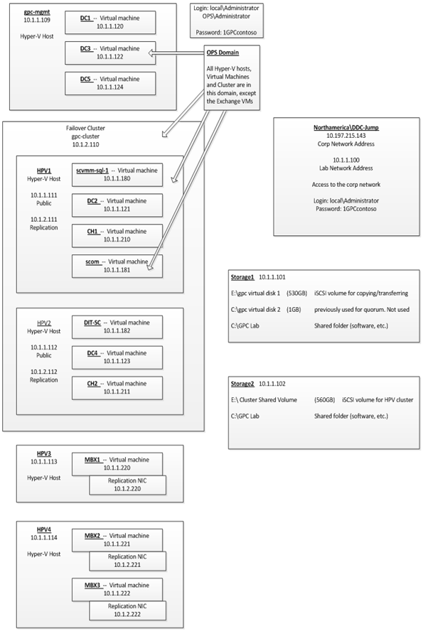
Figure 148: Virtual Machine Host Configuration - Redmond
Virtual Machine Host Configuration - GPC
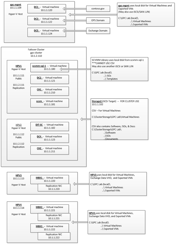
Figure 149: Virtual Machine Host Configuration - GPC
Installing Exchange Server 2010 begins with installing and preparing the operating system. Exchange Server 2010 can be installed only on Windows Server 2008 Standard Edition or Enterprise Edition. If you plan on trying out database availability groups and mailbox database copies, you will need to use the Enterprise Edition of Windows Server 2008. For more information about the requirements for Exchange Server 2010, see Exchange 2010 System Requirements.
Once the operating system has been installed, several pre-requisites must be installed. These include:
Operating system components, including RSAT-ADDS (needed on server that will perform schema updates), Web-Server, Web-Metabase, Web-Lgcy-Mgmt-Console, Web-ISAPI-Ext, NET-HTTP-Activation, Web-Basic-Auth, Web-Digest-Auth, Web-Windows-Auth, Web-Dyn-Compression, RPC-over-HTTP-proxy, Web-Net-Ext and Net-Framework. You can install all of these components at one time (e.g., for the Mailbox, Client Access and/or Hub Transport Server roles) by running the following command:
ServerManagerCmd -i RSAT-ADDS Web-Server Web-Metabase Web-Lgcy-Mgmt-Console Web-ISAPI-Ext NET-HTTP-Activation Web-Basic-Auth Web-Digest-Auth Web-Windows-Auth Web-Dyn-Compression RPC-over-HTTP-proxy Web-Net-Ext -Restart
For more information about the prerequisites for Exchange 2010, including those for the Edge Transport server role, see Exchange 2010 Prerequisites.
You might have noticed that Failover-Clustering is not listed as a pre-requisite. There is a feature in Exchange Server 2010 called a database availability group that does use Windows failover clustering technologies. However, thanks to another Exchange Server 2010 feature called incremental deployment, you no longer install failover clustering before installing Exchange. If you decide to use a database availability group, you simply create one, and then add Mailbox servers to it. When you add a Mailbox server to a DAG, we install the Windows failover clustering feature and automatically create a cluster for you. So while you do need to have Exchange installed on an operating system that supports Windows failover clustering, you do not install the failover clustering feature manually, or ahead of time, and you don't manually create a cluster. It makes deploying highly available mailbox databases quick and easy.
Exchange Server 2010 also supports installing the above pre-requisites by using an Answer File with ServerManagerCmd, and answer files are included in the Scripts folder. To use them, you run ServerManagerCmd -ip <Name of File>. For example:
ServerManagerCmd -ip Exchange-CAS.XML
I recommend that you don't use the XML Answer Files for Exchange-Typical or Exchange-MBX as is, because in the Beta build it mistakenly includs the Failover-Clustering feature, which does not need to be installed before Exchange is installed. This is a remnant from the Answer Files we had in Exchange 2007 that we've since removed.
Next, are the software pre-requisites, which includes:
- Update from KB 951725
- Update from KB 950888
- Update from KB 951116
- Update from KB 952664
- Update from KB 953290
- Update from KB 958178
See Exchange 2010 Prerequisites for information about and links to other pre-requisites that might apply to your environment (e.g., for Edge Transport and Unified Messaging server roles, and for environments that use System Center Operations Manager).
Once the above pre-requisites have been installed, check Microsoft Update for any additional updates that might be needed. Make sure the system has been rebooted after installing any updates which require a reboot.
Now you're ready to install Exchange 2010. You can perform the installation using the GUI or command-line version of Setup. In this example, I'll use the GUI.
I'll start by launching Setup.exe from the AMD64 folder. This launches the Exchange 2010 splash screen:
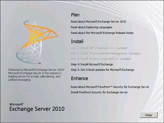
Figure 150: Exchange Server 2010 Setup
As you can see, the Exchange 2010 splash screen is very similar to the one we had in Exchange 2007. Any needed pre-requisites which are detected, are greyed out, indicating they have been installed, and that you can proceed to the next step. In this case, I can proceed directly to Step 4: Install Microsoft Exchange.
I click that link and it launches the GUI version of Exchange Setup, beginning with a file copy process, and the initialization of Setup.
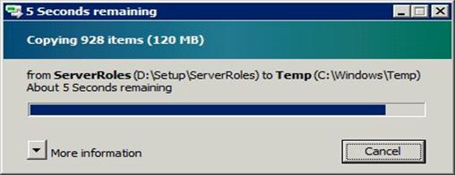
Figure 151: Exchange Server 2010 Setup
Once Setup is initialized and the file copy process has completed, the Introduction page appears:
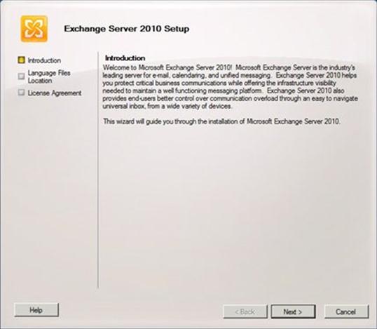
Figure 152: Exchange Server 2010 Setup
I click Next, and the Language Files Location page appears:
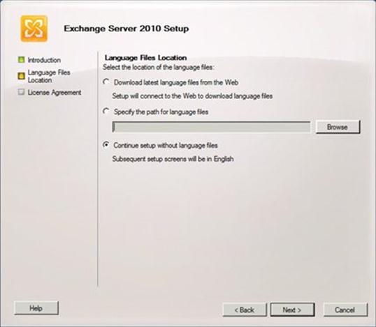
Figure 153: Exchange Server 2010 Setup
I don't have any additional language files, so I'll leave the default setting of Continue setup without language files and click Next. The Language Pack Confirmation page appears:
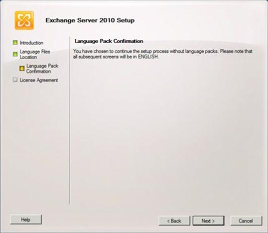
Figure 154: Exchange Server 2010 Setup
I click Next, and the License Agreement page appears:
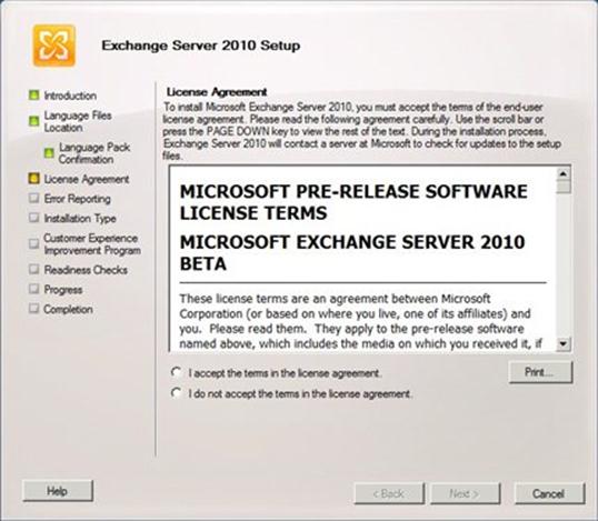
Figure 155: Exchange Server 2010 Setup
After reading the license agreement, I select I accept the terms in the license agreement and click Next. The Error Reporting page appears:
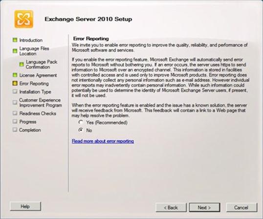
Figure 156: Exchange Server 2010 Setup
Error reporting is very helpful to us, which in turn is helpful to our customers, as it enables us to gather a minimal amount of diagnostic data to troubleshoot and resolve errors and crashes more quickly. So I am going to choose Yes (Recommended) and click Next. The Installation Type page appears:
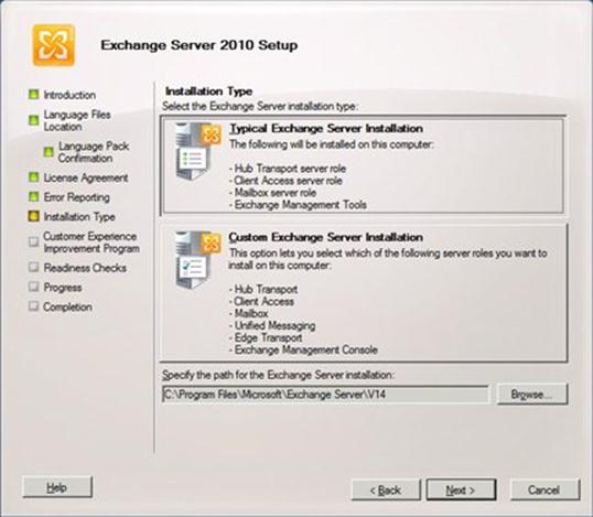
Figure 157: Exchange Server 2010 Setup
Immediately, you might notice some differences from Exchange Server 2007. First, the Custom Exchange Server Installation option no longer lists any clustered mailbox server roles. That's because clustered mailbox servers don't exist in Exchange Server 2010. Exchange 2010 includes a new feature called Incremental Deployment. This feature enables to you configure high availability and site resilience for your mailbox database after Exchange has been installed.
Second, the default path for the Exchange Server installation is new and different. If I choose Custom Exchange Server Installation, the Server Role Selection page appears:
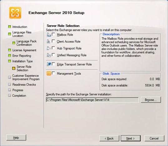
Figure 158: Exchange Server 2010 Setup
If I choose Typical Exchange Server Installation instead of Custom Exchange Server Installation and click Next, or once I've completed the Custom Exchange Server Installation choices and clicked Next, the Exchange Organization page appears:
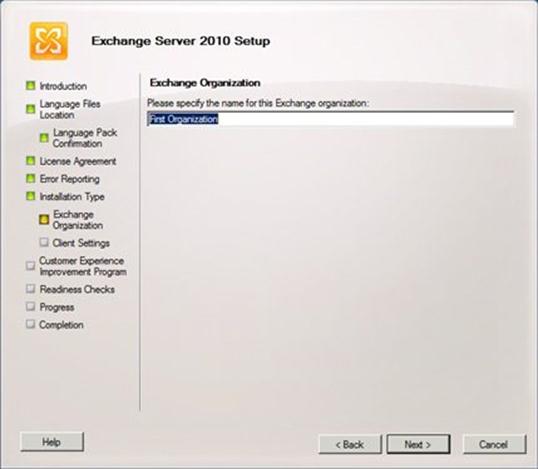
Figure 159: Exchange Server 2010 Setup
I specify a name for my Exchange Organization, and then I click Next. The Client Settings page appears:
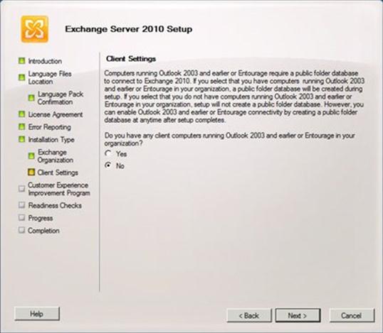
Figure 160: Exchange Server 2010 Setup
If the Exchange organization uses Outlook 2003 or earlier, or Microsoft Entourage, then a public folder database is needed so that those clients can access system data, such as Free/Busy information. In that case, you would select Yes on this page. Since my organization does not use Outlook 2003 or earlier, or Entourage, I can leave the default setting of No and click Next.
The Customer Experience Improvement Program (CEIP) page appears:
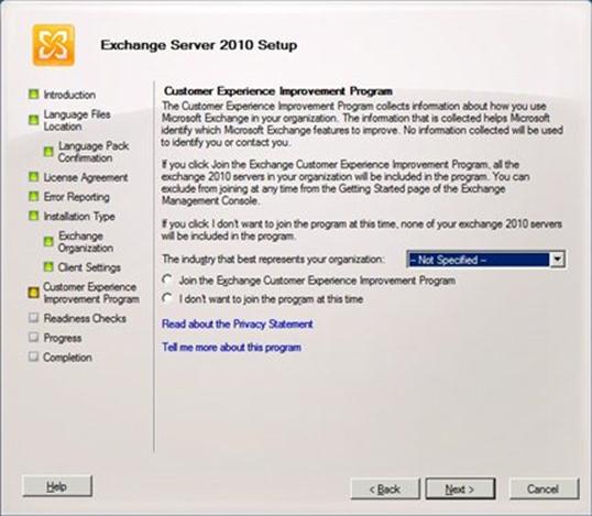
Figure 161: Exchange Server 2010 Setup
This program helps us improve our software by collecting data about how Exchange Server is used. I'll click Join the Exchange Customer Experience Improvement Program and specify an industry of Computer-Related Products/Services.
I click Next. The Readiness Checks page appears, and Setup automatically performs readiness checks for any installed language packs, as well as the selected server roles to be installed.
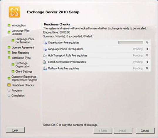
Figure 162: Exchange Server 2010 Setup
As you can see, the readiness checks don't take much time at all. Once all readiness checks have successfully passed, the Readiness Check page will look similar to this:
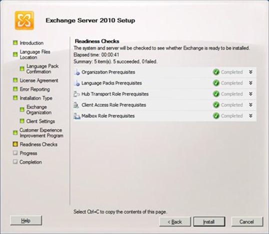
Figure 163: Exchange Server 2010 Setup
At this point, the system and server are ready for the installation to begin. I click Install to start the installation of Exchange 2010 Mailbox, Client Access and Hub Transport server roles, as well as the Exchange Management tools (Exchange Management Console and Exchange Management Shell).
While Setup is progressing, a Progress page will be appeared:
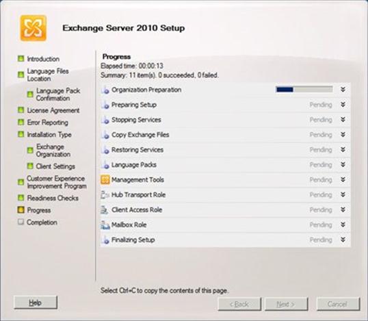
Figure 164: Exchange Server 2010 Setup
Once Setup has completed successfully, the Completion page will appear:
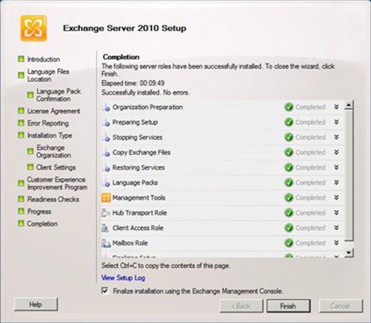
Figure 165: Exchange Server 2010 Setup
As you can see, installing Exchange 2010 is quick and easy. On my system, Setup took just under 10 minutes to complete.
I prefer to reboot the system before finalizing the installation. Uncheck the Finalize installation using the Exchange Management Console checkbox, and click Finish to complete the Setup process. This returns Setup to the splash screen. Click Close to close the splash screen, and when the Confirm Exit dialog appears:
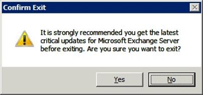
Figure 166: Exchange Server 2010 Setup
Click Yes.
Then, reboot the server. OK, technically, you don't need to reboot the server, but I do anyway.
The installation of Exchange Server 2010 is now complete.
- Exchange Configuration
Machine Names and associated IP addresses (all machines listed here are virtual unless otherwise noted):
- Parent Domain
- DC1.Contoso.Gov (physical machine)
- 10.1.1.120
- Primary DNS for all servers
- DC3.Ops.Contoso.Gov
- 10.1.1.122
- Secondary DNS for all servers
- Exchange Domain
- DC5.Resource.Gov
- 10.1.1.124
- CH1.OPS.Contoso.Gov
- 10.1.1.210
- CH2.OPS.Contoso.Gov
- 10.1.1.211
- MBX1.OPS.Contoso.Gov
- 10.1.1.220
- 10.1.2.220 (Replication Network)
- MBX2.OPS.Contoso.Gov
- 10.1.1.221
- 10.1.2.221 (Replication Network)
- MBX3.OPS.Contoso.Gov
- 10.1.1.222
- 10.1.2.222 (Replication Network)
Other Names
- Exchange Domain
- NLB1.OPS.Contoso.Gov
- 10.1.1.200
- DAG1.OPS.Contoso.Gov
- 10.1.1.201
Known Issues with Exchange 2010 SP1 DF7.5 build
Scenario: • Installed Partner Hosted Exchange on Windows Server 2008 R2 • Unable to navigate to OWA (eg. https://localhost/owa) Error:
Workaround: 1. Open "IIS Manager" in the box 2. Expand "Sites" node in IIS Manager 3. Select "Default Web Site" under Sites 4. Select "ISAPI Filters" in Default Web Site
5. Remove "Microsoft.Exchange.AuthModuleFilter ISAPI Filter"
Then you should be able to access OWA now.
| |
AD and DoMT should be deployed on separate boxes\If Isolated GAL is enabled, OAB should be deleted | To use Open Domain feature where GAL is hidden to user • AD and CAS should be deployed on separate boxes • Create a tenant (e.g. myOrg) without the following features in service plan o <AddressListsEnabled>true</AddressListsEnabled> o <OfflineAddressBookEnabled>true</OfflineAddressBookEnabled> Use the following to hide GAL o Get-GlobalAddressList -Organization myOrg | Set-GlobalAddressList -IsolationMode $true Password change through OWA doesn't does not work after first logon unless "Group Policy" is changed • Start > Administrative Tools > Group Policy Management > Forest > Domains > Group Policy Objects > Default Domain Policy > Right click to "Edit" and change the "Minimum password age" to 0 to allow immediate password change.
Default connectors should be created for mail delivery between tenants • New-SendConnector –Name Test –AddressSpaces * -Smarthosts localhost -DnsRoutingEnabled $false • Get-ReceiveConnector -Identity "<NetBiosName>\Default <NetBiosName>" | Set-ReceiveConnector -PermissionGroups "ExchangeUsers, ExchangeServers, ExchangeLegacyServers, AnonymousUsers"
|
We have 2 reports that hosting command lets are not available despite the fact that the /hosting switch is used for deployment. While the Exchange Team is looking into the issue and how to fix it here is a workaround for the problem. Unfortunately it means if you ran into this issue you will have to redeploy Exchange as there is no easy way to retrofit the missing settings. 1. Build a new Lab without Exchange AD preparation run 2. install the first Exchange Role with the following commandline "setup /mode:install /roles:ca,HT /hosting /on:<ExchangeOrganizationName>", replace <ExchangeOrganizationName> with the name for the intended Exchange Organization When you check the ExchangeSetup Log under the Install-ExchangeOrganization task you should see –IsPartnerHosted $true. [02/27/2010 01:31:24.0103] [0] Setup will run the task 'Install-ExchangeOrganization' [02/27/2010 01:31:24.0103] [1] Setup launched task 'Install-ExchangeOrganization -IsPartnerHosted $true
Should you see this or any related issue in your deployment please report it to the DL. |
Pasted from <https://ea.microsoft.com/hosters/Lists/Known%20Issues%20with%20DF75/AllItems.aspx>
Installation / Configuration Steps
- Software Required
- Windows 2008 R2 (forest / domain functional level)
Create a user object svc-certauth and make a member of IIS_IUSRS group
- Windows 2008 Roles
Active Directory Domain Services
Active Directory Certificate Services
Certification Authority
Certification Authority Web Enrollment
Online Responder
Certificate Enrollment Web Service
Certificate Enrollment Policy Web Service
Enterprise CA
DNS Server
Create the following DNS records
autodiscover.contoso.gov
mail.contoso.gov
casarray01.contoso.gov
dag01.contoso.gov
- Windows Update after the installation of Prereqs
- Additional hotfixes:
WCF Update
http://go.microsoft.com/fwlink/?LinkId=183148
Hotfix KB981002
https://connect.microsoft.com/VisualStudio/Downloads/DownloadDetails.aspx?DownloadID=27127
Hotfix KB979099 (Update for AD RMS)
http://support.microsoft.com/?kbid=979099
Microsoft Filter Pack
Install and Configure Exchange 2010 SP1 Hosting Edition
- Build a new Lab without Exchange AD preparation (Windows 2008 R2 dc's and OS)
Domain Functional Level | Windows 2008 |
Forest Functional Level | Windows 2008 |
Exchange Member Servers OS | Windows 2008 R2 |
- Install the first Exchange Role with the following commandline
PowerShell Script
"setup /mode:install /roles:ca,HT /hosting /on:<ExchangeOrganizationName>"
When you check the ExchangeSetup Log under the Install-ExchangeOrganization task you should see –IsPartnerHosted $true.
[02/27/2010 01:31:24.0103] [0] Setup will run the task 'Install-ExchangeOrganization'
[02/27/2010 01:31:24.0103] [1] Setup launched task 'Install-ExchangeOrganization -IsPartnerHosted $true
Pasted from <https://ea.microsoft.com/hosters/Lists/Known%20Issues%20with%20DF75/AllItems.aspx>
Create a new Client Access Array
PowerShell Script
New-ClientAccessArray -FQDN casarray01.contoso.com -Name "casarray01.contoso.com" -Site "Toronto"
Create a certificate request
PowerShell Script
New-ExchangeCertificate -GenerateRequest -SubjectName "c=US, o=Contoso, cn=mail.contoso.gov" -DomainName cdautodiscover.contoso.gov, ecp.contoso.gov, mail.contoso.gov -PrivateKeyExportable $true
Get the thumbprint and enable the new cert with Get-ExchangeCertificate and Enable-ExchangeCertificate
Enable-ExchangeCertificate -Thumbprint 5867672A5F29B388C235E1235 -Services "IMAP, POP, IIS, SMTP"
Create a new Database Availability Group
PowerShell Script
New-DatabaseAvailablityGroup
Add mailbox servers to the DAG
PowerShell Script
Add-DatabaseAvailabilityGroupServer -Identity DAG01 -MailboxServer MBX1
Add-DatabaseAvailabilityGroupServer -Identity DAG01 -MailboxServer MBX2
Add-DatabaseAvailabilityGroupServer -Identity DAG01 -MailboxServer MBX3
Rename the default mailbox databases
PowerShell Script
Set-MailboxDatabase -Identity "Mailbox Database 0483463198" -Name MDB01
Set-MailboxDatabase -Identity "Mailbox Database 1593765178" -Name MDB02
Set-MailboxDatabase -Identity "Mailbox Database 2142150893" -Name MDB03
Add mailbox database copies
PowerShell Script
Add-MailboxDatabaseCopy -Identity MDB01 -MailboxServer MBX2
Add-MailboxDatabaseCopy -Identity MDB01 -MailboxServer MBX3
Add-MailboxDatabaseCopy -Identity MDB02 -MailboxServer MBX1
Add-MailboxDatabaseCopy -Identity MDB02 -MailboxServer MBX3
Add-MailboxDatabaseCopy -Identity MDB03 -MailboxServer MBX1
Add-MailboxDatabaseCopy -Identity MDB03 -MailboxServer MBX2
Configure the RPC Client Access Array
PowerShell Script
Set-MailboxDatabase -Identity MDB01 -RpcClientAccessServer casarray01.contoso.com
Set-MailboxDatabase -Identity MDB02 -RpcClientAccessServer casarray01.contoso.com
Set-MailboxDatabase -Identity MDB03 -RpcClientAccessServer casarray01.contoso.com
- Document Information
- Terms and Abbreviations
Abbreviation | Definition |
SCVMM | System Center Virtual Machine Manager |
SCOM | System Center Operations Manager |
VMM | Virtual Machine Manager |
WAN | Wide Area Network |
SAN | Storage Area Network |
SAS | Serial Attached SCSI |
VHD | Virtual Hard disk |
VSV | Virtual save state file |
VSS | Volume shadow Copy Service |
Table 11: Terms and Abbreviations
Appendix A – Hyper-V Host Server Farm Pattern
The Host Server Farm architecture pattern is illustrated below.
The architecture consists of a multi-node Windows Server 2008 R2 cluster leveraging a shared storage system such as an iSCSI or Fibre Channel storage area network (SAN) and storage array. Each node of the cluster runs Windows Server 2008 R2 with Hyper-V.
- This pattern provides server consolidation and high availability on a greater scale.
- Supports up to 16 nodes in a single cluster configuration.
- Virtual machines can run on any node of the cluster.
- In the event of a node failure, the virtual machines will be restarted automatically on any node that has the available capacity to host the failed resources.
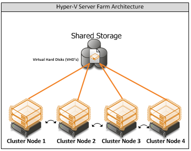
Figure i: Hyper-V Server Farm pattern
Information
The Host Server Farm pattern provides high availability as well as better use of hardware since a single physical host can serve a passive node for up to 15 active nodes.
Appendix B – Host Cluster patterns
- No Majority – Disk Only
The cluster has quorum if one node is available and in communication with a specific disk in the cluster storage. Only the nodes that are also in communication with that disk can join the cluster.
Microsoft Recommendations
This pattern is not recommended for High Availability as the disk can be a single point of failure.
- Node Majority
Node Majority is a quorum model where each node that is available and in communication can vote. The cluster functions only with a majority of the votes, that is, more than half.
Microsoft Recommendations
This pattern is recommended in Failover Cluster deployments containing an odd number of nodes.
- Node and Disk Majority
Node and Disk Majority is a quorum model in Windows Server 2008 R2 Failover Clustering. In this quorum model, a cluster remains active until half of the nodes and its witness disk is available. In case, the witness disk is offline, a cluster requires a majority of nodes to be up and running in order to successfully run the cluster. This model contains two or more nodes connected to a shared storage device. The witness disk is stored on the cluster disk. This quorum model is used in scenarios where all nodes are connected to a shared storage device on the same network.
Microsoft Recommendations
This pattern is recommended in Failover Cluster deployments containing an even number of nodes.
- Node and File Share Majority
The file share witness feature is an improvement to the current Majority Node Set (MNS) quorum model. This feature lets you use a file share that is external to the cluster as an additional "vote" to determine the status of the cluster.
Microsoft Recommendations
This pattern is recommended in Failover Cluster deployments containing an even number of nodes and for Multi-Site failover clusters.
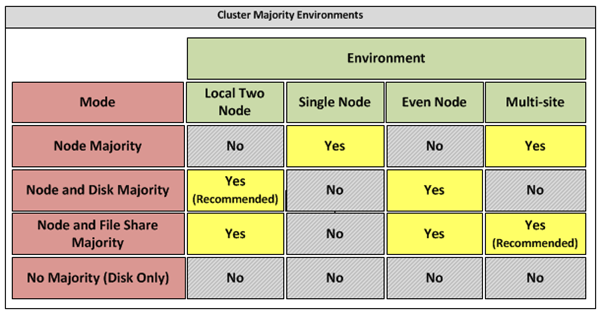
Figure ii: Host Cluster Patterns
Appendix C – Network Architecture
The network architecture of the host server is a frequently overlooked topic in host server sizing because Gigabit Ethernet NICs are now very inexpensive and most servers have at least two built in. The topic is important, however, because it is directly impacted by the host server architecture pattern selected. If one of the two host server cluster patterns is selected, a dedicated NIC per server is required for the cluster private (heartbeat) network. Gigabit Ethernet is a high-speed network transport, though a host server with a large number of guests may require greater than Gigabit speed, thus requiring additional NICs. Finally, it is recommended that each host server have a NIC dedicated to the host itself for network I/O and management.
A fairly large number of NICs per host server may be required. Recently, 10-Gigabit Ethernet has become commonly available and is starting to drift lower in price, similar to the way Gigabit Ethernet has done over the years. The ability for servers to utilize 10-Gigabit Ethernet NICs is a significant factor in increasing the consolidation ratio.
Microsoft Recommendations
Use multiple NICs and multi-port NICs on each host server.
- One NIC dedicated to the host machine only for management purposes
- One NIC dedicated to the private Cluster Heartbeat network
- One NIC dedicated to the Live Migration network
- One or more NICs dedicated to the guest virtual machines (use 10 gpbs NICS for highest consolidation)
- Two or more NICs dedicated to iSCSI with MPIO
Dedicate at least one NIC/Port on each host server for guest virtual machine network I/O. For maximum consolidation ratio, utilize one or more 10-Gigabit Ethernet NICs to virtual machine network I/O.
Warning
Microsoft does not support the use of NIC teaming software. Support for these third-party technologies must be provided by the vendor.
Appendix D - Processor Architecture
Windows Server 2008 R2 with Hyper-V requires x64 processor architecture from Intel or AMD, as well as support for hardware execute disable and hardware virtualization such as Intel VT or AMD-V.
Both Intel and AMD provide a wide range of processors that are appropriate for host servers. The industry competition between the two is very tight and at any one time; one may have a performance advantage over the other. Regardless of which manufacturer is chosen, several performance characteristics are important.
The number of processor cores is a key performance characteristic. Windows Server 2008 R2 with Hyper-V makes excellent use of multi-core processors, so the more cores the better. Another important characteristic is the processor clock speed, which is the speed at which all cores in the processor will operate. It's important because it will be the clock speed of all of the guest virtual machines. This is a key variable in the consolidation ratio because it impacts the amount of candidates that the host server can handle and the speed at which those guests will operate. As an example, choosing 2 GHz processor rather than a 3 GHz processor on a server that will host 20 guests means that all of those guests will run only at 2 GHz.
At a lower level of detail, the server processor architectures make design choices in terms of the type and quantity of processor cache, memory controller architecture, and bus/transport architecture. A detailed analysis of these factors is beyond the scope of this document.
Microsoft Recommendations
x64 processor architectures are required for all Hyper-V host server architecture patterns. If you are purchasing new servers, we recommend working with your server vendor to ensure that the selected hardware is capable of running Windows Server 2008 R2 and Hyper-V, and that it is validated for Windows Server 2008 R2 failover clustering. For new servers, we recommend selecting the maximum number of cores per processor available and choosing the fastest or second fastest clock speed available.
Appendix E – Memory Architecture
Once the system architecture and processor architecture choices are made, there are relatively few options remaining for memory architecture because it is usually predetermined by the manufacturer/system/processor combination. The memory architecture choices that remain are typically quantity, speed, and latency. For Hyper-V, the most important memory architecture choice is the quantity of RAM. Most consolidated workloads (that is, individual guest virtual machines) will require at least 512 MB to 1 GB of RAM or more. Since most commodity four-socket servers can only cost effectively support between 32 and 128 GB of RAM, this is frequently the limiting factor in host server capacity.
The quantity of RAM is a more important factor than RAM speed or latency. Once the maximum amount of RAM that is cost effective is determined, if there is a remaining choice between speed and latency, choosing the memory with lower latency is recommended.
Microsoft Recommendations
Given the system and processor architectures already selected, we recommend utilizing the maximum amount of RAM that can be cost effectively added to the host system. Typically, there is a price point where the cost of moving to the next DIMM size (that is, 2 GB DIMMs to 4 GB DIMMs) is more than twice the cost, and in some cases, it approaches the cost of an entire server. We recommend fully populating the server up to that price point. For example, if the server has 8 DIMM slots and 4 GB DIMMs are much more than twice the cost of 2 GB DIMMs, we recommend fully populating the server with 2 GB DIMMs and considering a second host server if additional capacity is required.
For all host server architecture patterns, we recommend a minimum of 16 GB of RAM.
For Multi-Node Host Server Farm patterns, we recommend a minimum of 64 GB per server.
Appendix F - Drive types
The type of hard drive utilized in the host server or the storage array the host servers will have a significant impact on the overall storage architecture performance. The critical performance factors for hard disks are the interface architecture (for example, U320 SCSI, SAS, SATA), the rotational speed of the drive (7200, 10k, 15k RPM), and the average latency in milliseconds. Additional factors, such as the cache on the drive, and support for advanced features, such as Native Command Queuing (NCQ), can improve performance. As with the storage connectivity, high IOPS and low latency are more critical than maximum sustained throughput when it comes to host server sizing and guest performance. When selecting drives, this translates into selecting those with the highest rotational speed and lowest latency possible. Utilizing 15k RPM drives over 10k RPM drives can result in up to 35% more IOPS per drive.
SCSI
SCSI drives are rapidly being replaced by SATA, SAS, and Fibre Channel drives. SCSI drives are not recommended for new host server architectures; however, existing servers with U320 SCSI drives can provide excellent performance characteristics.
SATA
SATA drives are a low cost and relatively high performance option for storage. SATA drives are available primarily in the 1.5 GB/s and 3.0 GB/s standards (SATA I and SATA II) with a rotational speed of 7200 RPM and average latency of around 4 ms. There are a few SATA I drives that operate at 10k RPM and average latency of 2 ms that can provide an excellent low cost storage solution.
SAS
SAS drives are typically much more expensive than SATA drives but can provide significantly higher performance in both throughput, and more importantly, low latency. SAS drives typically have a rotational speed of 10k or 15k RPM with an average latency of 2 to 3 ms.
Fibre Channel
Fibre Channel drives are usually the most expensive and typically have similar performance characteristics to SAS drives but use a different interface. The choice of Fibre Channel or SAS drives is usually determined by the choice of storage array. As with SAS, they are typically offered in 10k and 15k RPM variants with similar average latencies.
Microsoft Recommendations
Fibre Channel 15k RPM drives are recommended for Host Server Farm patterns.
If you are using a Fibre Channel SAN, ensure that the switch and director infrastructure is sized to handle the large amount of storage I/O that will be generated from the consolidated servers.
Appendix G - Disk Redundancy Architecture
Redundant Array of Inexpensive Disk (RAID) is strongly recommended for all Hyper-V host storage. By definition, Hyper-V hosts run and store data from multiple workloads. RAID is necessary to ensure that availability is maintained during disk failure. In addition, if properly selected and configured, RAID arrays can provide improvements in overall performance.
RAID 1
RAID 1 is disk mirroring. Two drives store identical information so that one is a mirror of the other. For every disk operation, the system must write the same information to both disks. Because dual write operations can degrade system performance, many employ duplexing, where each mirror drive has its own host adapter. While the mirror approach provides good fault tolerance, it is relatively expensive to implement because only half of the available disk space can be used for storage, while the other half is used for mirroring.
RAID 5
Also known as striping with parity, this level is a popular strategy for low- or mid-range storage systems. RAID 5 stripes the data in large blocks across the disks in an array. RAID 5 writes parity data across all the disks in the RAID 5 set. Data redundancy is provided by the parity information. The data and parity information is arranged on the disk array so that the two types of information are always on different disks. Striping with parity can offer better performance than disk mirroring (RAID 1). However, when a stripe member is missing, read performance is decreased (for example, when a disk fails). RAID 5 is a less expensive option because it utilizes drive space more efficiently than RAID 1.
RAID 1+0 (RAID 10)
For more information about these types of RAID systems, contact your storage hardware vendor.
RAID 1 or RAID 1+0 is recommended for the system volume in all host server architecture patterns.
RAID 1+0 is recommended for the data volumes in the Host Server Farm patterns.
Appendix H - Fibre Channel Storage Area Network
Architecture | Throughput (theoretical max Megabyte/sec) |
iSCSI (Gigabit Ethernet) | 125 MB/s |
Fibre Channel (2 GFC) | 212.5 MB/s |
SATA (SATA II) | 300 MB/s |
SCSI (U320) | 320 MB/s |
SAS | 375 MB/s |
Fibre Channel (4 GFC) | 425 MB/s |
Table i: Comparison of Disk Controller throughput speeds
Appendix I - Disk Controller or HBA Interface
Architecture | Throughput (theoretical max Megabyte/sec) |
iSCSI (Gigabit Ethernet) | 125 MB/s |
Fibre Channel (2 GFC) | 212.5 MB/s |
SATA (SATA II) | 300 MB/s |
SCSI (U320) | 320 MB/s |
SAS | 375 MB/s |
Fibre Channel (4 GFC) | 425 MB/s |
Table ii: Comparison of Disk Controller Interfaces
4 GFC Fibre Channel is recommended for the Host Server Farm architecture pattern.
Appendix J - Cluster Shared Volumes
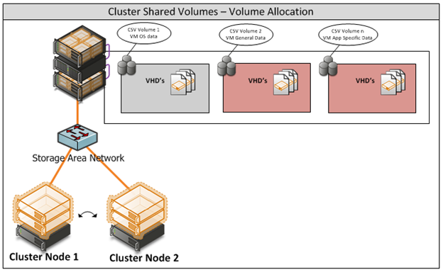
Figure iii: CSV Volume Allocation
Appendix K - System Center Virtual Machine Manager R2 2008
Virtual Machine Manager Server
Delegated Management and Provisioning Web Portal
Appendix L – Hyper-V Overview
Figure iv: Hyper-V Environment
Appendix M – Hardware Architecture
The recommended server configuration for the Hyper-V Management Server is:
Server Architecture |
2 x Xeon Quad Core Processors x64 |
32 GB of RAM |
2 x 150 GB (300GB) RAID 1 OS Partition with Array - SAS RAID Controller |
Local or External Storage (ISCSI/FC) |
Up to 4 x 1GBps Network ports (Management/Virtual/External and potentially ISCSI Networks) |
Table iv: Management Host Server Architecture
The Virtualised Management Servers which will be used have the following resource requirements:
The recommended server specification for each cluster node is:
Server Architecture |
2 x Xeon Quad Core Processors x64 |
48GB of RAM |
2 x 150 GB (300GB) RAID 1 OS Partition with Array - SAS RAID Controller |
Optional 2GBps FC HBA (if using FC SAN) |
External Storage (ISCSI/FC) – 5TB |
Up to 3 x 1GBps Network ports (Management/Virtual/Live Migration/ Heartbeat and potentially ISCSI Networks) Minimum required is 2. |
Table v: Cluster Host Server Architecture
The Hyper-V host servers should utilise local storage for the operating system and the paging file.
The drives utilised by the operating system should be configured as RAID 1.
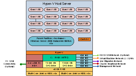 Figure iv: Cluster Host Server Overview
Appendix N – References
- For Deployment Scenario more details please refer to the link http://www.microsoft.com/downloads/details.aspx?FamilyID=fef38539-ae5a-462b-b1c9-9a02238bb8a7&displaylang=en and download a file VMM08R2_VMMSSPDocumentation.zip for more information.
- Failover clustering documents http://technet.microsoft.com/en-us/library/cc732181(WS.10).aspx#BKMK_Install
- Build SCVMM & SQLVM http://technet.microsoft.com/en-us/library/cc764289.aspx
- SQL 2008 Install http://technet.microsoft.com/en-us/library/bb500469(SQL.100).aspx
http://technet.microsoft.com/en-us/library/ms143506(SQL.100).aspx
- Exchange 2010 SP1 download link http://technet.microsoft.com/en-us/evalcenter/dd185495.aspx
- Lab Configuration excel sheet

- Unified Access Gateway http://technet.microsoft.com/en-us/library/dd857385.aspx