Hough Transform
Introduction:
The Hough transform is an algorithm that will take a collection of points, and find all the lines on which these points lie.
we define a line as a collection of points that are adjacent and have the same direction.
In order to understand the Hough transform, we will first consider the normal (perpendicular) representation of a line:
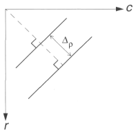
If we have a line in our row and column (rc)-based image space, we can define that line by ρ, the distance from the origin to the line along a perpendicular to the line, and θ, the angle between the r-axis and the ρ-line.


Now, for each pair of values of ρ and θ we have defined a particular line.
The range on θ is ±90° and ρ ranges from 0 to sqrt(2)N, where N is the image size.
Next, we can take this ρθ parameter space and quantize it, to reduce our search time,We quantize the ρθ parameter space, by dividing the space into a specific number of blocks.
Hough Space

Each block corresponds to a line, or group of possible lines, with ρ and θ varying across the increment as defined by the size of the block.
The size of these blocks corresponds to the coarseness of the quantization; bigger blocks provide less line resolution.
The algorithm used for the Hough consists of three primary steps:
1. Define the desired increments on ρ and θ, ∆ρ and ∆θ, and quantize the space accordingly.
2. For every point of interest (typically points found by edge detectors that exceed some threshold value), plug the values for r and c into the line equation:
Then, for each value of θ in the quantized space, solve for ρ.
3. For each ρθ pair from step 2, record the rc pair in the corresponding block in the quantized space. This constitutes a hit for that particular block.
When this process is completed, the number of hits in each block corresponds to the number of pixels on the line as defined by the values of ρ and θ in that block.
Hough Transform Flowchart

The flowchart is followed until all l(r, c) have been examined.
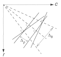
The advantage of large quantization blocks is that the search time is reduced, but the price paid is less line resolution in the image space.
Examining this figure , we can see that this means that the line of interest in the image space can vary more.
Effects of Quantization Block Size for Hough Transform
 |
 |
 |
|
a. Range of lines included by choice of ∆ρ. |
b. Range of lines included by choice of ∆θ. |
c. Range of lines included by choice of block size. |
One block in the Hough Space corresponds to all the solid lines in this figure—this is what we mean by reduced line resolution.
Next, select a threshold and examine the quantization blocks that contain more
points than the threshold.
Here, we look for continuity by searching for gaps in the line by looking at the
distance between points on the line(the points on a line correspond to points
recorded in the block).
When this process is completed, the lines are marked in the output image.
The program:
My program begin with a menu to choose the type of input image, if you have a regular image(Grayscale image) you can make edge detection (Robert, Sobel, Prewitt) and grayscale threshold by the program, and if you have a binary image you can start from point 3.
Next step, you enter the name of the image (must be in the program directory), each step you pass the result is shown, and in the grayscale threshold you can repeat the threshold operation if the binary image not as you prevent.
In the Hough transform menu you can select a specified angle or you can input ∆θ mean that you enter the angles {-90, -90+∆θ , -90+2∆θ ………,90}.
How it can be programmed?
1-edge detection:
we convolute the masks of the operator with the image at
each pixel, Robert Operator is simple its like this
out.SetPixel(i,j, abs( input.GetPixel(i,j) - input.GetPixel(i-1,j-1))
+abs( input.GetPixel(i-1,j)- input.GetPixel(i,j-1) ));
And in Sobel Operator we have two numbers s1,s2
corresponding to the results of the two masks and the edge magnitude =


we can implement this algorithm by multiplying a two dimensional array contains the values of the mask.
but since the two masks contains zeros so it has no effect in computing the results (its just take some time from the calculations) so we can discard these zeros as in this code.
S1=-(input.GetPixel(i-1,j-1)+2*input.GetPixel(i-1,j)+input.GetPixel(i-1,j+1))
+(input.GetPixel(i+1,j-1)+2*input.GetPixel(i+1,j)+input.GetPixel(i+1,j+1))
S2=-(input.GetPixel(i-1,j-1)+2*input.GetPixel(i,j-1)+input.GetPixel(i+1,j-1))
+(input.GetPixel(i-1,j+1)+2*input.GetPixel(i,j+1)+input.GetPixel(i+1,j+1))
by implementing array multiplication and the code after discard the zeros multiplication I find experimentally that the time is reduced by about 35%
Prewitt Operator can be implemented in the same way.
Hough Transform:
“Hough Transform” is the main function it takes a binary
image and some parameter of the lines that the user wants to select it, this
mean that if the user want to select the lines that have a slope from
–90,-90+deltaTheta …… to 90 it can enter the value of deltaTheta he want.
Another parameter is deltaRo, to decrease or increase the
line resolution as we talk above.
connectDistance parameter is to select the maximum number in
pixels in the gap that cut the line that the program can connect them.
pixelsCcount (threshold) is the minimum number of line
pixels, if the line contain number of pixels less than this number its not
selected .
theta is the angle
of the lines that the user want to select them (he enter one angle at a time
then the result shown and if he want to select another angles, he can.).
How to implement Hough transform algorithm?
1-first of all we must allocate the Hough space witch has a width of 180/deltaTheta an a height of chord/deltaRo.
The algorithm does not clear what we do if ρ has negative value, so we can ignore these values or allocate another Hough space for the negative values. which is the best ignore them or allocate to them?
If we have this image:
Angle = -45o
If ρ2 = x => ρ1= -x.
So the first line ignored !!
If we put – ρ block pixels and +ρ block pixels in the same block this mean that these tow lines becomes on line !! .
I confirm experimentally from these assumption and I found that actually that some lines are losses if I merge the –ve and +ve ρ blocks.
So we must allocate two deferent blocks to the +ve ρ and -ve ρ pixels.
This
mean that the dimensions the height of Hough space become 2*chord/deltaRo wher
chord =  if the image has a dimensions of NxN.
Implementation of Hough blocks:
Hough block can be implemented by a two dimensional array of linked list of points, this mean that each Hough block contain the value of the first pint lies in this Ro and Theta and contain a pointer that points to the next point in this block.
If the block contain no points the value of x,y in this block should be –1,the last point in the linked list points must be NULL, so it must be initialized.
struct LinkedPoint{
int X,Y;
LinkedPoint *nextPoint;
};
since I use malloc() function which is allocate one
dimensional array of bytes so I convert Hough space from two dimension to one
dimension, and I can reach any block by a simple equation.
If Hough space contain ‘roNum’ of rows and
thetaNum of columns I can reach HS[x][y]=HS[x*yheatNum + y];
Before any point added to a Hough block we must allocate some memory bytes by the function:
tempLinkedPoint->nextPoint=(LinkedPoint* )malloc(12);//12 byte
tempLinkedPoint=tempLinkedPoint->nextPoint;
tempLinkedPoint->X=i;
tempLinkedPoint->Y=j;
tempLinkedPoint->nextPoint=NULL;
after we end the addition loop we must check if the gap between each two points(neighbors in the linked list) is less than the gap that the user select it, we repeat this step and go forward to the next point … until the we find a large gap then we count the previous points if there count is more than the threshold that selected by the user we draw a line between the first point and the last point and start the gap checking from the next point and its next and start the count again.
Finally if we not find any large gap and the points count is more than the user selected number we connect these points.
if (hough[index].X!=-1) //if its –1 =>there is no points
{
counter=1;
tempLinkedPoint=&hough[index];
startPoint=&hough[index];
while (tempLinkedPoint->nextPoint!=NULL)
{
x1=tempLinkedPoint->X;
y1=tempLinkedPoint->Y;
x2=tempLinkedPoint->nextPoint->X;
y2=tempLinkedPoint->nextPoint->Y;
actualDistance=sqrt(pow((x2-x1),2)+pow((y2-y1),2));
if(actualDistance<=connectDistance)
counter+=1;
else
{
if(counter>=pixelsCount)
{
t1=startPoint;
DrawLine(transImg,t1->X,t1->Y
,tempLinkedPoint->X,tempLinkedPoint->Y);
}
startPoint=tempLinkedPoint->nextPoint;//the new line
counter=1;
}
tempLinkedPoint=tempLinkedPoint->nextPoint ;
}
if(counter>=pixelsCount) //rech to the end
{
t1=startPoint;
DrawLine(transImg,t1->X,t1->Y
,tempLinkedPoint->X,tempLinkedPoint->Y);
}
}
how to draw the line?
This function “DrawLine ” simply draw a line between two given points by select
the point set that lies in the line.
This algorithm from “INTRODUCTION TO COMPUTER GRAPHICS” book
and have some changes.
void DrawLine(CImage* transImg,int x1,int y1,int x2,int y2)
{
int dx=x2-x1;
int dy=y2-y1;
float m;
if (abs(dx)>abs(dy))
{
int xInc =dx/abs(dx);
m=(float)dy/fabs(dx);
int X;
float Y=(float)y1;
for(X=x1;X!=x2;X+=xInc)
{
transImg->SetPixelFast(X,GetIntValue(Y),1);
Y+=m;
}
}
else
{
int yInc =dy/abs(dy);
m=(float)dx/fabs(dy);
float X=(float)x1;
int Y;
for(Y=y1;Y!=y2;Y+=yInc)
{
transImg->SetPixelFast(GetIntValue(X),Y,1);
X+=m;
}
transImg->SetPixelFast(GetIntValue(X),Y,1);
}
}
Experimental Example:
Regular image

Robert edge detector applied
Threshold at gray level 75
Hough output ∆ρ =1 , ∆θ =1,threshold = 12 and max distance connected = 4
We see that the separated points is discarded and we took only the lines with given parameters
Another example:
 |
 |
 |
|
Binary image cointains lines and some noise |
The output image after Hough
transform with Threshold=20, distance=10, DeltaRo=0.5, Theta=45o |
Theta=45o And Theta=0o |
 |
 |
 |
|
Theta = 45, 0 , -45 |
Theta = 45, 0 , -45 , 90 |
Theta = 45, 0 , -45 , 90 ,120 |
 |
||
|
The output if we use Threshold=20, distance=10, DeltaRo=0.5 , deltaTheta = 5o |
Hough Transform Source Code(VC++) ( Download )
Hough Transform Console Application
Image Processing Library tools (needed)