1. 项目:使用stm32寄存器点亮LED, 分别点亮红、绿、蓝3个灯。
2. 步骤
- 先新建个文件夹保存项目
- 再新建项目
- 将startup_stm32f10x_hd.s拷贝到该文件夹下
- 新建main.c子项目
- 再次在文件夹中新建stm32f10.h文件
- 编写main.c,将stm32f10.h导入编译
- 编写stm32f10.h子项目
3. 代码
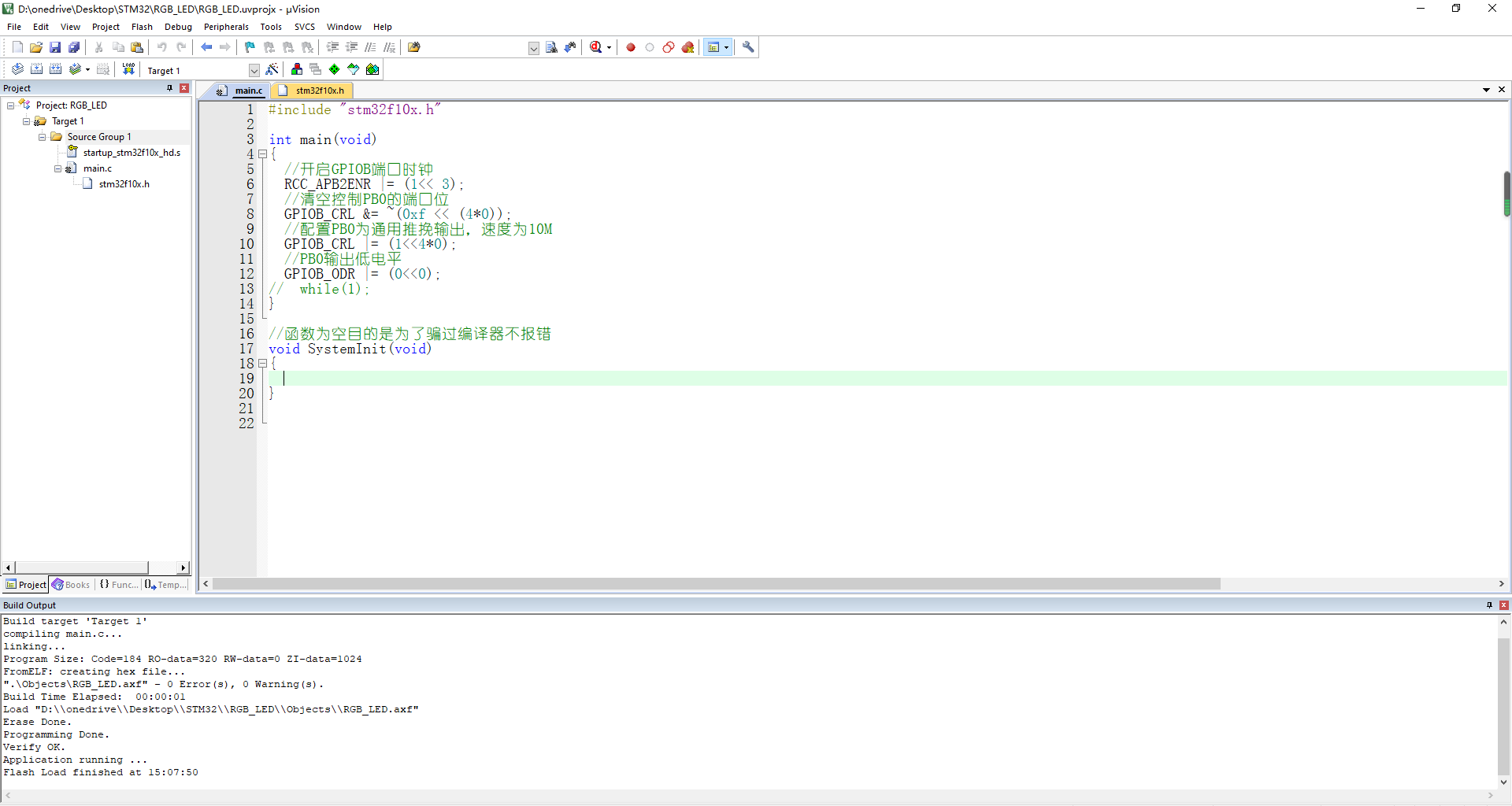
main.c
#include "stm32f10x.h"

int main(void)
{
	//开启GPIOB端口时钟
	RCC_APB2ENR |= (1<< 3);
	//清空控制PB0的端口位
	GPIOB_CRL &= ~(0xf << (4*0));
	//配置PB0为通用推挽输出,速度为10M
	GPIOB_CRL |= (1<<4*0);
	//PB0输出低电平
	GPIOB_ODR |= (0<<0);
//	while(1);
}

//函数为空目的是为了骗过编译器不报错
void SystemInit(void)
{

}
stm32f10.h
//列表3:代码清单:点亮LED-3外设地址定义
/*片上外设基地址*/
#define PERIPH_BASE			((unsigned int )0x40000000)

/*总线基地址,GPIO 都挂载到APB2上*/
#define APB2PERIPH_BASE		(PERIPH_BASE + 0x10000)

/*AHB系统总线,APB1,APB2总线都挂载到AHB系统总线上*/
#define AHBPERIPH_BASE		(PERIPH_BASE + 0x20000)

/*GPIOB外设基地址*/
#define GPIOB_BASE 			(APB2PERIPH_BASE + 0x0c00)


/*GPIOB寄存器地址,强制转换成指针*/
#define GPIOB_CRL			*(unsigned int*)(GPIOB_BASE + 0x00)
#define GPIOB_CRH			*(unsigned int*)(GPIOB_BASE + 0x04)
#define GPIOB_IDR			*(unsigned int*)(GPIOB_BASE + 0x08)
#define GPIOB_ODR			*(unsigned int*)(GPIOB_BASE + 0x0c)
#define GPIOB_BSRR			*(unsigned int*)(GPIOB_BASE + 0x10)
#define GPIOB_BRR			*(unsigned int*)(GPIOB_BASE + 0x14)
#define GPIOB_LCKR			*(unsigned int*)(GPIOB_BASE + 0x18)

/*RCC外设基地址*/
#define RCC_BASE			(AHBPERIPH_BASE + 0x1000)
/*RCC的AHB1时钟使能寄存器地址,强制转换成指针*/
#define RCC_APB2ENR			*(unsigned int*)(RCC_BASE + 0x18)
4. 这里我使用的时野火的指南者开发板,点亮的绿灯,如果需要点亮红蓝灯,只需要修改main.c 中的PB1, PB5端口设置即可。
5. 参考图片