I would like to set STM8L052C6T6 to Ultra Low Power. I tried different setting on I/O and refer to the discovery broad example, I still struggle on this issue, I am worried hand-solder to damage STM8L052C6T6 chip, Here is my code, all I/O is open!
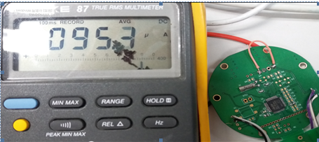
TEST 1: Init all the I/O to GPIO_Mode_Out_PP_Low_Slow, then Set all I/O to GPIO_SetBits, the current is 95.3uA.
void main(void)
{
CLK_DeInit();
GPIO_DeInit(GPIOA);
GPIO_DeInit(GPIOB);
GPIO_DeInit(GPIOC);
GPIO_DeInit(GPIOD);
GPIO_DeInit(GPIOE);
GPIO_DeInit(GPIOF);
/* Port A in output push-pull 0 */
GPIO_Init(GPIOA, GPIO_Pin_All ,GPIO_Mode_Out_PP_Low_Slow);
GPIO_Init(GPIOB, GPIO_Pin_All, GPIO_Mode_Out_PP_Low_Slow);
GPIO_Init(GPIOC, GPIO_Pin_All, GPIO_Mode_Out_PP_Low_Slow);
GPIO_Init(GPIOD, GPIO_Pin_All, GPIO_Mode_Out_PP_Low_Slow);
GPIO_Init(GPIOE, GPIO_Pin_All, GPIO_Mode_Out_PP_Low_Slow);
GPIO_Init(GPIOF, GPIO_Pin_All, GPIO_Mode_Out_PP_Low_Slow);
GPIO_SetBits(GPIOA,GPIO_Pin_All);
GPIO_SetBits(GPIOB,GPIO_Pin_All);
GPIO_SetBits(GPIOC,GPIO_Pin_All);
GPIO_SetBits(GPIOD,GPIO_Pin_All);
GPIO_SetBits(GPIOE,GPIO_Pin_All);
GPIO_SetBits(GPIOF,GPIO_Pin_All);
disableInterrupts();
while(1){
nop();
nop();
nop();
halt();
nop();
nop();
nop();
}
}
TEST 2: Init all the I/O to GPIO_Mode_Out_PP_Low_Slow, then Set all I/O to GPIO_SetBits, the current is 12.44mA.
void main(void)
{
CLK_DeInit();
GPIO_DeInit(GPIOA);
GPIO_DeInit(GPIOB);
GPIO_DeInit(GPIOC);
GPIO_DeInit(GPIOD);
GPIO_DeInit(GPIOE);
GPIO_DeInit(GPIOF);
/* Port A in output push-pull 0 */
GPIO_Init(GPIOA, GPIO_Pin_All ,GPIO_Mode_Out_PP_Low_Slow);
GPIO_Init(GPIOB, GPIO_Pin_All, GPIO_Mode_Out_PP_Low_Slow);
GPIO_Init(GPIOC, GPIO_Pin_All, GPIO_Mode_Out_PP_Low_Slow);
GPIO_Init(GPIOD, GPIO_Pin_All, GPIO_Mode_Out_PP_Low_Slow);
GPIO_Init(GPIOE, GPIO_Pin_All, GPIO_Mode_Out_PP_Low_Slow);
GPIO_Init(GPIOF, GPIO_Pin_All, GPIO_Mode_Out_PP_Low_Slow);
GPIO_ResetBits(GPIOA,GPIO_Pin_All);
GPIO_ResetBits(GPIOB,GPIO_Pin_All);
GPIO_ResetBits(GPIOC,GPIO_Pin_All);
GPIO_ResetBits(GPIOD,GPIO_Pin_All);
GPIO_ResetBits(GPIOE,GPIO_Pin_All);
GPIO_ResetBits(GPIOF,GPIO_Pin_All);
disableInterrupts();
while(1){
nop();
nop();
nop();
halt();
nop();
nop();
nop();
}
}

Answer:
Dose pcb have no peripheral circuit?
Please try to set the IO PORT to GPIO_Mode_In_PU_No_IT.
Last problem(Ultra Low Power) is fixed, I got another problem about the LSE(Low Speed external) clock not correct.
CLK_LSEConfig(CLK_LSE_ON);
RTC_Config();
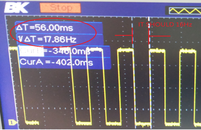
RTC_SetWakeUpCounter(1024/8-1); //16Hz
RTC_WakeUpCmd(ENABLE);
I setup by above code and measure toggle I/O in the 16Hz interrupt, but I got 17.86Hz, I also try this in the discovery board, then measure the frequency is 20Hz. How can I know the reason?
When RTC wake up from halt() mode, you need disable the RTC wake up and enable RTC wake up before entering the halt() mode.
Please also try adding the following two functions before entering the halt() mode.
PWR_FastWakeUpCmd(ENABLE);
PWR_UltraLowPowerCmd(ENABLE);
All of the above operations are due to the application code that takes up the runtime of the RTC. And ensure the RTC clock source is LSE.