lab14 简单玩一把封装--独立按键的封装
本实验利用前面的按键消抖模块和DE2上的资源,设计一个利用pwm控制led发光亮度的实验。
1 简介
时钟:50MHz,CLOCK_50;
复位:SW1,拨下为复位;
5个输入:SW0,KEY[3:0];
输出:LEDG8;
5个输入代表5种不同的PWM,即不同占空比的1KHz的脉冲信号,那么LED的亮的时间也不同,人眼看到的亮度就不同。
2 设计
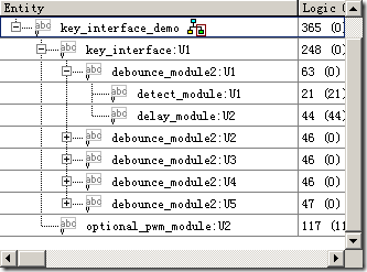
工程结构
源码
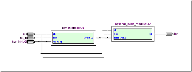
1)key_interface_demo.v,本例的顶层模块。调用按键模块和可调pwm模块。
 1 module key_interface_demo
 2 (
 3     input clk,
 4     input rst_n,
 5     input [4:0] key_in,
 6     output led
 7 );
 8
 9     wire [4:0] key_out;
10
11     key_interface U1
12     (
13         .clk(clk),
14         .rst_n(rst_n),
15         .key_in(key_in),
16         .key_out(key_out)
17     );
18
19     optional_pwm_module U2
20     (
21         .clk(clk),
22         .rst_n(rst_n),
23         .option_key(key_out),
24         .led(led)
25     );
26
27 endmodule
28
2) key_interface.v,按键模块,5个按键例化5次。
 1 module key_interface
 2 (
 3     input clk,
 4     input rst_n,
 5     input [4:0] key_in,
 6     output [4:0] key_out
 7 );
 8
 9     debounce_module2 U1
10     (
11         .clk(clk),
12         .rst_n(rst_n),
13         .pin_in(key_in[4]),
14         .pin_out(key_out[4])
15     );
16
17     debounce_module2 U2
18     (
19         .clk(clk),
20         .rst_n(rst_n),
21         .pin_in(key_in[3]),
22         .pin_out(key_out[3])
23     );
24
25     debounce_module2 U3
26     (
27         .clk(clk),
28         .rst_n(rst_n),
29         .pin_in(key_in[2]),
30         .pin_out(key_out[2])
31     );
32
33     debounce_module2 U4
34     (
35         .clk(clk),
36         .rst_n(rst_n),
37         .pin_in(key_in[1]),
38         .pin_out(key_out[1])
39     );
40
41     debounce_module2 U5
42     (
43         .clk(clk),
44         .rst_n(rst_n),
45         .pin_in(key_in[0]),
46         .pin_out(key_out[0])
47     );
48
49 endmodule
50
3) debounce_module2.v,按键消抖模块。
 1 module debounce_module2
 2 (
 3     clk,rst_n,pin_in,pin_out
 4 );
 5
 6     input clk;
 7     input rst_n;
 8     input pin_in;
 9     output pin_out;
10
11     wire h2l;
12     wire l2h;
13
14     detect_module U1
15     (
16         .clk(clk),
17         .rst_n(rst_n),
18         .pin_in(pin_in),
19         .h2l(h2l),
20         .l2h(l2h)
21     );
22
23     delay_module U2
24     (
25         .clk(clk),
26         .rst_n(rst_n),
27         .h2l(h2l),
28         .l2h(l2h),
29         .pin_out(pin_out)
30     );
31
32 endmodule
4) detect_module.v,电平检测模块。
 1 module detect_module
 2 (
 3     clk,rst_n,pin_in,h2l,l2h
 4 );
 5
 6     input clk;
 7     input rst_n;
 8     input pin_in;
 9     output h2l;
10     output l2h;
11
12     parameter T100US = 13'd5000;
13
14     reg [12:0] count1;  //定时器
15     reg isen;
16
17     always @(posedge clk or negedge rst_n)
18         if (!rst_n)
19             begin
20                 count1 <= 13'd0;
21                 isen <= 1'b0;
22             end
23         else if (count1 == T100US)
24             isen <= 1'b1;
25         else
26             count1 <= count1 + 1'b1;
27
28     reg h2l_f1;
29     reg h2l_f2;
30     reg l2h_f1;
31     reg l2h_f2;
32
33     always @(posedge clk or negedge rst_n)
34         if (!rst_n)
35             begin
36                 h2l_f1 <= 1'b1;
37                 h2l_f2 <= 1'b1;
38                 l2h_f1 <= 1'b0;
39                 l2h_f2 <= 1'b0;
40             end
41         else
42             begin
43                 h2l_f1 <= pin_in;
44                 h2l_f2 <= h2l_f1;
45                 l2h_f1 <= pin_in;
46                 l2h_f2 <= l2h_f1;
47             end
48
49     assign h2l = isen ? (h2l_f2 & !h2l_f1) : 1'b0;
50     assign l2h = isen ? (!l2h_f2 & l2h_f1) : 1'b0;
51
52 endmodule
53
5) delay_module.v,10ms延时模块。
 1 module delay_module
 2 (
 3     clk,rst_n,h2l,l2h,pin_out
 4 );
 5
 6     input clk;
 7     input rst_n;
 8     input h2l;
 9     input l2h;
10     output pin_out;
11
12     parameter T1MS = 16'd50_000;
13
14     reg [15:0] count1;  //1ms定时器
15
16     always @(posedge clk or negedge rst_n)
17         if (!rst_n)
18             count1 <=  16'd0;
19         else if (iscount && count1 == T1MS)
20             count1 <= 16'd0;
21         else if (iscount)
22             count1 <= count1 + 1'b1;
23         else if (!iscount)
24             count1 <= 16'd0;
25
26     reg [3:0] count_ms;  //10ms计数器
27
28     always @(posedge clk or negedge rst_n)
29         if (!rst_n)
30             count_ms <= 4'd0;
31         else if (iscount && count1 == T1MS)
32             count_ms <= count_ms + 1'b1;
33         else if (!iscount)
34             count_ms <= 4'd0;
35
36     reg iscount;  //计数使能
37     reg rpin_out;
38     reg [1:0] i;
39
40     always @(posedge clk or negedge rst_n)
41         if (!rst_n)
42             begin
43                 iscount <= 1'b0;
44                 rpin_out <= 1'b0;
45                 i <= 2'd0;
46             end
47         else
48             case(i)
49                 2'd0:
50                     if (h2l)
51                         i <= 2'd1;
52                     else if (l2h)
53                         i <= 2'd3;
54                 2'd1:              //延迟10ms,输出高电平
55                     if (count_ms == 4'd10)
56                         begin
57                             iscount <= 1'b0;
58                             rpin_out <= 1'b1;
59                             i <= 2'd2;
60                         end
61                     else
62                         iscount <= 1'b1;
63                 2'd2:
64                     begin
65                         rpin_out <= 1'b0;
66                         i <= 2'd0;
67                     end
68                 2'd3:              //延迟10ms
69                     if (count_ms == 4'd10)
70                         begin
71                             iscount <= 1'b0;
72                             i <= 2'd0;
73                         end
74                     else
75                         iscount <= 1'b1;
76             endcase
77
78     assign pin_out = rpin_out;
79
80 endmodule
81
6) optional_pwm_module.v,可调pwm模块。
 1 module optional_pwm_module
 2 (
 3     input clk,
 4     input rst_n,
 5     input [4:0] option_key,
 6     output led
 7 );
 8
 9     parameter SEGMENT = 8'd195;    //3.9us
10
11     reg [7:0] c1;  //3.9us定时器
12
13     always @(posedge clk or negedge rst_n)
14         if (!rst_n)
15             c1 <= 7'd0;
16         else if (c1 == SEGMENT)
17             c1 <= 7'd0;
18         else
19             c1 <= c1 + 1'b1;
20
21     reg [7:0] system_seg;  //pwm块计数器
22
23     always @(posedge clk or negedge rst_n)
24         if (!rst_n)
25             system_seg <= 8'd0;
26         else if (system_seg == 8'd255)
27             system_seg <= 8'd0;
28         else if (c1 == SEGMENT)
29             system_seg <= system_seg + 1'b1;
30
31     reg [7:0] option_seg;  //可调pwm块
32
33     always @(posedge clk or negedge rst_n)
34         if (!rst_n)
35             option_seg <= 8'd0;
36         else if (option_key[4])    //segment + 10
37             if (option_seg < 8'd245)
38                 option_seg <= option_seg + 8'd10;
39             else
40                 option_seg <= 8'd255;
41         else if (option_key[3])    //segment - 10
42             if (option_seg > 8'd10)
43                 option_seg <= option_seg - 8'd10;
44             else
45                 option_seg <= 8'd0;
46         else if (option_key[2])    //segment + 1
47             if (option_seg < 8'd255)
48                 option_seg <= option_seg + 8'd1;
49             else
50                 option_seg <= 8'd255;
51         else if (option_key[1])    //segment - 1
52             if (option_seg > 8'd0)
53                 option_seg <= option_seg - 8'd1;
54             else
55                 option_seg <= 8'd0;
56         else if (option_key[0])    //segment = half
57             option_seg <= 8'd127;
58
59     assign led = (system_seg < option_seg) ? 1'b1: 1'b0;
60
61 endmodule
62
63
RTL Viewer
引脚分配
 1 #CLOCK_50
 2 set_location_assignment pin_n2 -to clk
 3 #SW1
 4 set_location_assignment pin_n26 -to rst_n
 5 #SW0
 6 set_location_assignment pin_n25 -to key_in[4]
 7 #KEY[3:0]
 8 set_location_assignment pin_w26 -to key_in[3]
 9 set_location_assignment pin_p23 -to key_in[2]
10 set_location_assignment pin_n23 -to key_in[1]
11 set_location_assignment pin_g26 -to key_in[0]
12 #LEDG8
13 set_location_assignment pin_y12 -to led
问题
warning:found pins functioning as undefined clocks and/or memory enables.
原因:为指定时钟。
解决方法:
assignment / setting / timing analysis setting / classic timing analyzer settings / default required fmax / individual clocks / new / applies to node / clk / clock setting /
... / ok.
或者set_instance_assignment -name CLOCK_50 -to clock
3 小结
由例化调用,小体验一把封装是怎么回事儿。

