8 状态机设计:电子火车控制器
8.3 火车控制问题
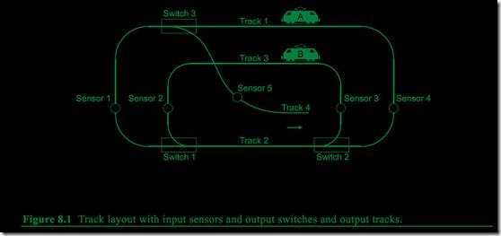
图8.1列出一个小型的电子火车系统轨道图。2列火车,分别命名为A和B,运行在轨道上,希望不会碰撞。要避免碰撞,需要一个安全控制器来控制火车无事故的出入交叉点。
为了安全运行,同一时间只能有一列火车出现在给定的轨道段上。图8.1所示的轨道图将轨道分为4部分。每段轨道都有感应器检测火车的出入点。
在图8.1中,有2列火车A和B。例如,假设火车A总是运行在外围轨道,火车B总是运行在内圈轨道。在某一时刻,火车A逆时针运行刚好通过感应器4接近开关3.我们假设火车B也是逆时针运行接近感应器2.既然火车B将要进入公共轨道段(轨道段2)。当火车A到达感应器1必须停止。直到火车B通过感应器3(比如,火车B离开公共轨道段)。这时,轨道开关应切向火车A,允许火车A进入轨道2,而火车B继续向感应器2运行。
控制器是一个使用感应器作为输入的状态机。控制器的输出控制火车的运行方向和开关的位置。当然,状态机不控制火车的速度。这样控制系统的功能正确与否不依赖于2列火车的速度。
一个基于FPGA的虚拟火车仿真将用来验证这个设置并提供视频输出。因为FPGA板上没有实际的连接火车的电路,所以打算只视觉演示输出信号在实际系统里是如何工作的。以下的章节描述状态机是如何恰当的控制每个信号,管理火车运行的。
8.2 火车运行方向输出(DA1-DA0和DB1-DB0)
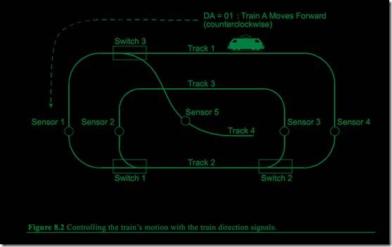
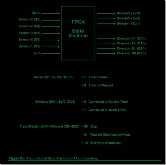
火车的运行方向由4个输出信号控制(每列火车2个),火车A用DA(DA1-DA0),火车B用DB(DB1-DB0)。值为01表示逆时针方向(对于轨道段4,火车向脱轨的方向),值为10,表示顺时针方向,值11表示非法,禁用,值00表示停止。(如图8.2所示)
8.3 开关方向的输出(SW1,SW2,SW3)
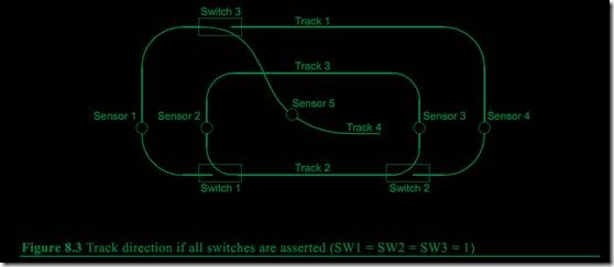
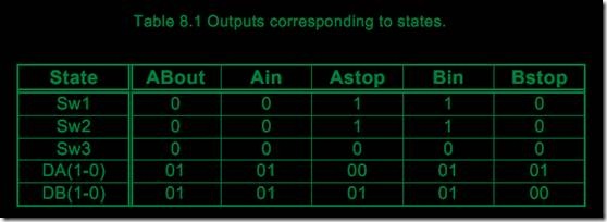
开关方向由SW1,SW2,SW3的值决定,高为连接内圈轨道,低为连接外圈轨道。因此,任何时候将所有的开关设为1,像图8.3所示,外圈的轨道连接到内圈。如果一列火车以错误方向通过一个打开的开关,将脱轨。注意在图8.3中,如果火车在标签“Track 1”的轨道向左运行,将在开关3脱轨。要避免脱轨,开关3应设为0.
另外,注意轨道段3和4有交叉点,要避免撞车。
8.4 火车感应器的输入信号(S1,S2,S3,S4,S5)
当火车接近感应器时,感应器的输入信号(S1,S2,S3,S4,S5)为高电平。注意感应器的高电平不是只持续一个时钟周期。事实上,每经过一列火车,感应器持续高电平多个时钟周期。因此,要测试设计里的同一个感应器的状态转换,必须等到信号由高电平变为低电平。
比如,要计算火车通过感应器1的次数,不能只用递增语句。必须有个状态判断S1=1,然后S1=0,又S1=1,以确定通过了S1两次。如果状态机有2个同时查找S1=1的状态,尽管火车只经过S1一次,每个状态都要经历2个连续的时钟周期。
另一种方法是如果检测到S1=1,然后S4=1,然后S1=1,那么确定火车在外圈运行。每种方法都要确定火车通过S1两次。
状态机的输入、输出信号总结如下图:
8.5 控制器设计范例
接下来看一个火车控制器的范例。对于这个控制器,2列火车以不同的速度逆时针方向运行。火车A运行在外圈,火车B运行在内圈。同一时间,只允许1列火车占据公共轨道。
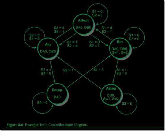
图8.5和8.6分别列出ASM和状态图。在ASM图里,状态名About,Ain,Bin,Bstop,和Astop表示状态。长方框包含给定状态的有效输出(高电平)。没列出的输出通常假设为无效(低电平)。
菱形框表示条件判断。当框中有2个信号时,它们都在同一时间测试为指定值。
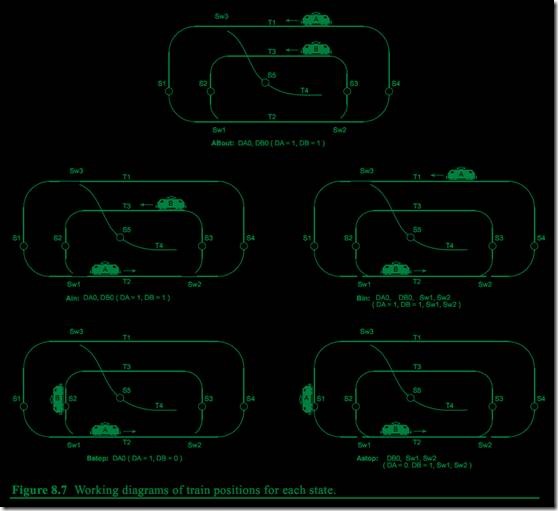
图8.6所示的经典状态图。和8.5包含同样的信息。ASM和状态图的区别只是表示的风格不同。图8.7的轨道图将状态视觉显示。状态名里的in和out参考轨道2的状态,这段轨道为公共轨道。
状态描述
All States
l 所有未声明的信号都是0并意味着期望合乎逻辑的结果。
ABout:火车A和B的外部
l DA0有效:火车A在外部轨道并逆时针前进。
l DB0有效:火车B在内部轨道(非公共轨道)运行。
l 注意并未指定DA1,它自动赋0—DB1也如此,这样,输出就是DA=01和DB=01.
Ain:火车A进入公共轨道
l 感应器1触发或同时感应器2触发。
l 火车A将尝试进入公共轨道,或
l 2列火车都将试图进入公共轨道。
l 2列火车都允许进入,但是,如果都进入了,状态Bstop将停止B。
l DA0有效:火车A在外部轨道并逆时针前进。
l DB0有效:火车B在内部轨道(非公共轨道)运行。
Bstop:火车B停在S2,等待火车A离开公共轨道
l DA0有效:火车A从外圈前进到公共轨道。
l 火车B到达感应器2,停止,直到感应器4触发。
l SW1和SW2无效,使得外部轨道连接到公共轨道。
Bin:在火车A到达感应器1之前,火车B到达感应器2.
l 火车B被允许进入公共轨道。火车A将到达感应器1.
l DA0有效:火车A在外部轨道并逆时针前进。
l DB0有效:火车B在内部轨道向公共轨道前进。
l SW1有效:内圈轨道连接到公共轨道。
l SW2有效:内圈轨道连接到公共轨道。
Astop:火车A停在S1直到火车B离开公共轨道。
l DB0有效:火车B在内部轨道向公共轨道前进。
l SW1和SW2有效:内圈轨道连接到公共轨道。
verilog 代码:
//example verilog state machine to control trains

module Tcontrol(reset,clock,sensor1,sonsor2,sensor3,sensor4,sensor5,
                            switch1,switch2,switch3,dirA,dirB);
                            //this section defines state machine inputs and outputs
                            //no modifications should be needed in this section
                            input reset,clock,sensor1,sensor2,sensor3,sensor4,sensor5;
                            output switch1,switch2,switch3;
                            output [1:0] dirA,dirB;
                            reg switch1,switch2;
                            //dirA and dirB are 2-bit logic vector(i.e. an array of 2 bits)
                            reg [1:0] dirA,dirB;
                            reg [2:0] state;
                            //this code describes how the state machine operates
                            //this section will need changes for a different state machine
                            //state assignments are needed in verilog

                            parameter ABout=0,Ain=1,Bin=2,Astop=3,Bstop=4;
                            //this section describes how the state machine behaves
                            //this process runs once every time reset or the clock changes

                            always @(posedge clock or posedge reset)
                            begin
                                //reset to this state(i.e. asynchronous reset)
                                if(reset)
                                    state=ABout;
                                else
                                    //posedge clock means positive clock edge
                                    //this section will execution once on each positive clock edge
                                    //signal assignments in this section will generate D flip-flops
                                    case(state)    //case statement to determine next state
                                        ABout:
                                                    //this case checks both sensor1 and sensor2 bits
                                                    case(sensor12)
                                                        2'b00:    state=ABout;
                                                        2'b01:    state=Bin;
                                                        2'b10:    state=Ain;
                                                        2'b11:    state=Ain;
                                                        //default case is needed here
                                                        default:    state=ABout;
                                                    endcase
                                        Ain:
                                                    case(sensor24)
                                                        2'b00:    state=Ain;
                                                        2'b01:    state=ABout;
                                                        2'b10:    state=Bstop;
                                                        2'b11:    state=ABout;
                                                        default:    state=ABout;
                                                    endcase
                                        Bin:
                                                    case(sensor13)
                                                        2'b00:    state=Bin;
                                                        2'b01:    state=ABout;
                                                        2'b10:    state=Astop;
                                                        2'b11:    state=ABout;
                                                        default:    state=ABout;
                                                    endcase
                                        Astop:
                                                    if(sensor3)
                                                        state=Ain;
                                                    else
                                                        state=Astop;
                                        Bstop:
                                                    if(sensor4)
                                                        state=Bin;
                                                    else
                                                        state=Bstop;
                                        default:    state=ABout;
                                    endcase
                                end
//combine sensor bits for case statement above
//{} operators combine bits

wire [1:0] sensor12={sensor1,sensor2};
wire [1:0] sensor13={sensor1,sensor3};
wire [1:0] sensor24={sensor2,sensor4};
//these outputs do not depend on the state
wire switch3=0;
//outputs that depend on state, use state to select value
//be sure to specify every output for every state
//value will not default to zero!
always @(state)
begin
                                    case(state)
                                        ABout:
                                            begin
                                                switch1=0;
                                                switch2=0;
                                                dirA=2'b01;
                                                dirB=2'b01;
                                            end
                                        Ain:
                                            begin
                                                switch1=0;
                                                switch2=0;
                                                dirA=2'b01;
                                                dirB=2'b01;
                                            end
                                        Bin:
                                            begin
                                                switch1=1;
                                                switch2=1;
                                                dirA=2'b01;
                                                dirB=2'b01;
                                            end
                                        Astop:
                                            begin
                                                switch1=1;
                                                switch2=1;
                                                dirA=2'b00;
                                                dirB=2'b01;
                                            end
                                        Bstop:
                                            begin
                                                switch1=0;
                                                switch2=0;
                                                dirA=2'b01;
                                                dirB=2'b00;
                                            end
                                        default:
                                            begin
                                                switch1=0;
                                                switch2=0;
                                                dirA=2'b00;
                                                dirB=2'b00;
                                            end
                                    endcase
end

endmodule
